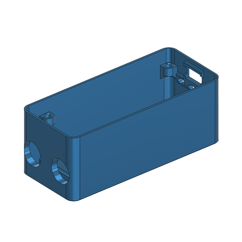
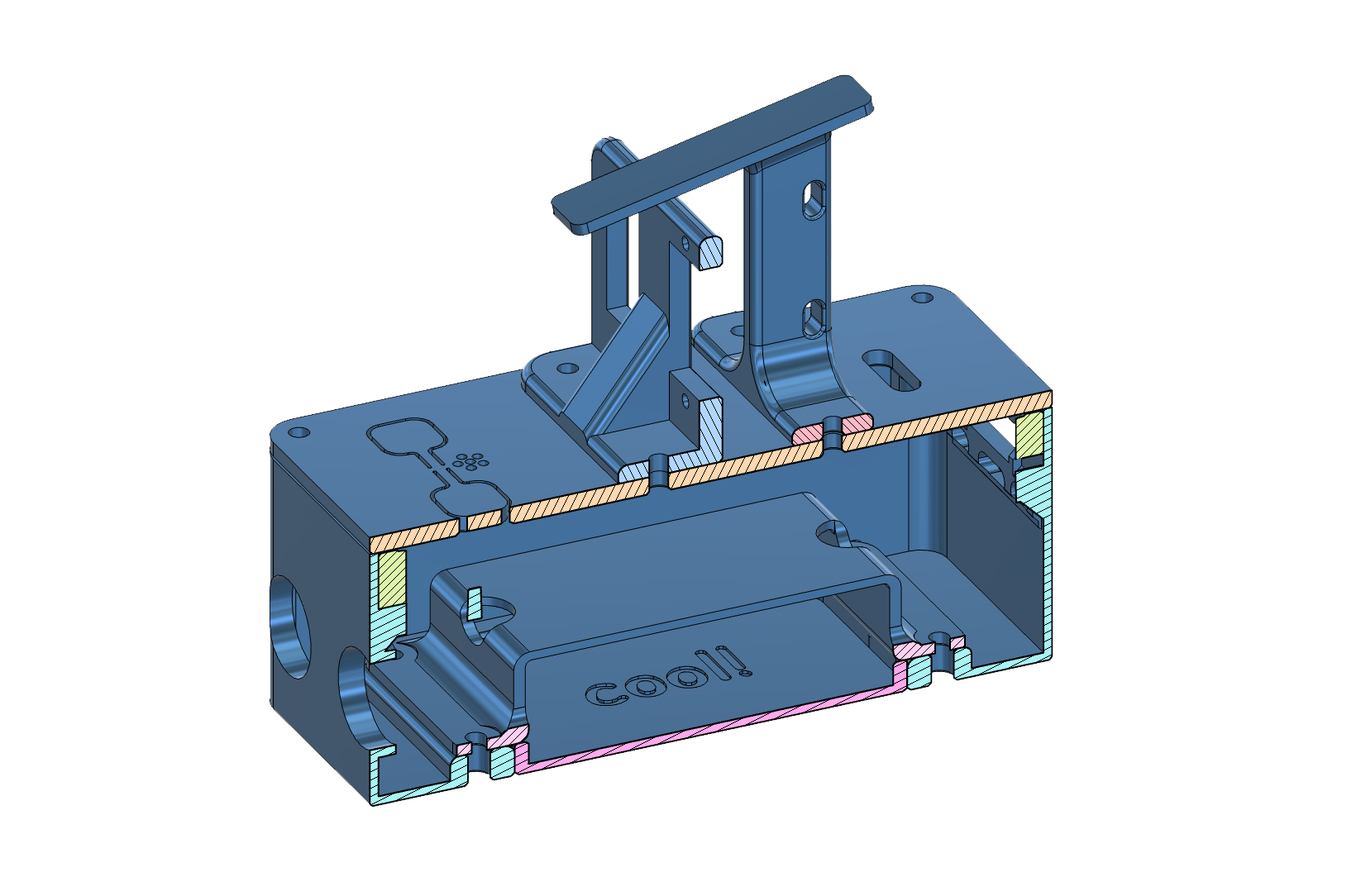
 Enclosure
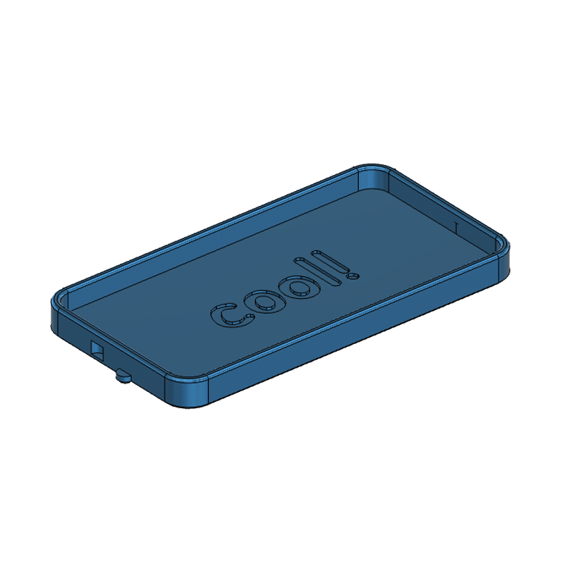
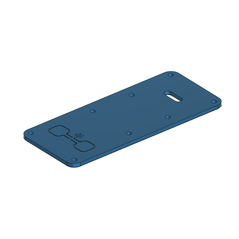 Lid
Lid
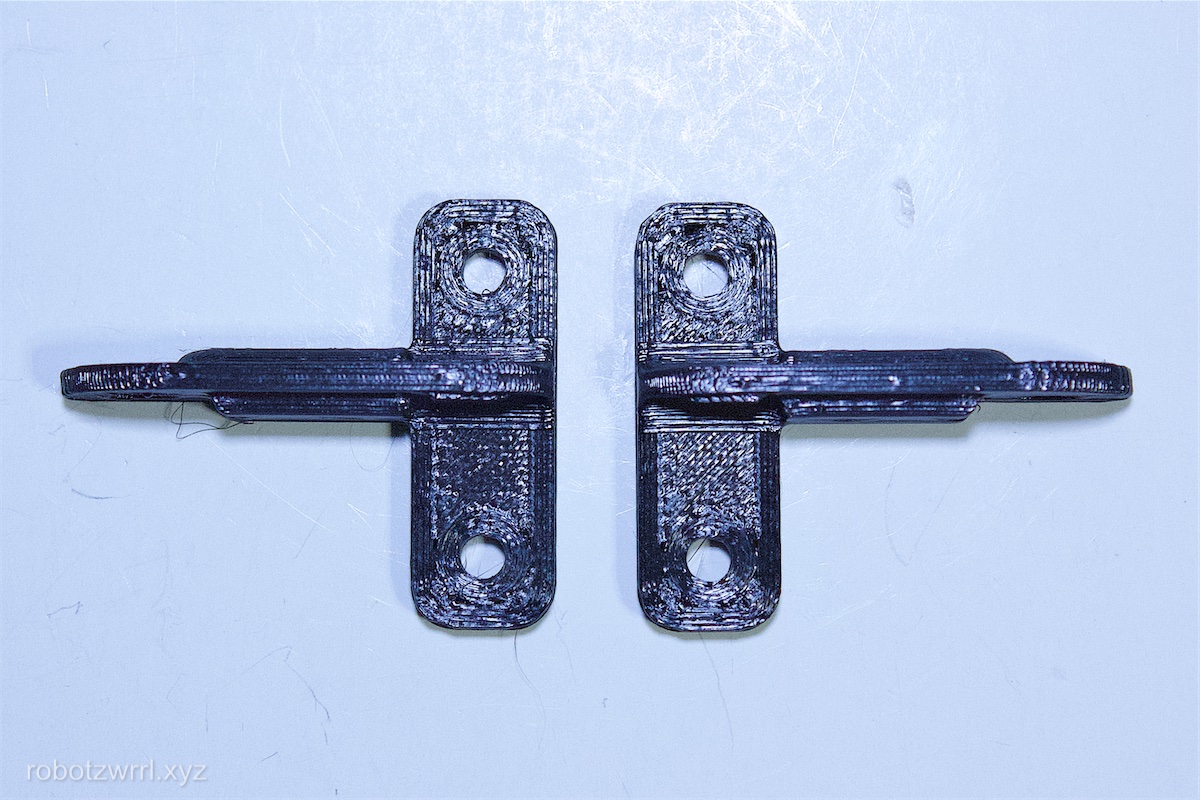
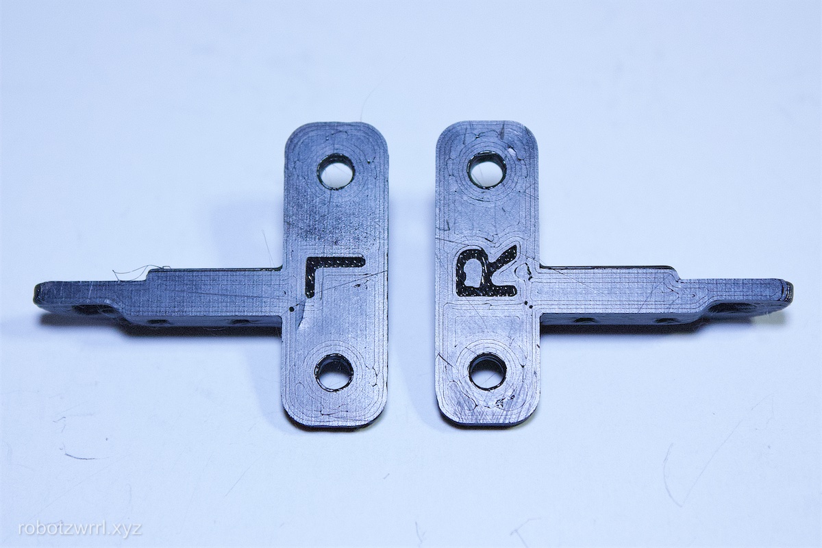
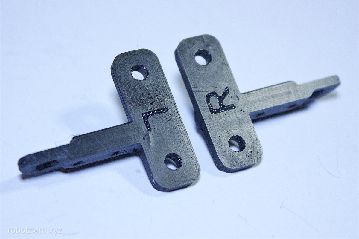
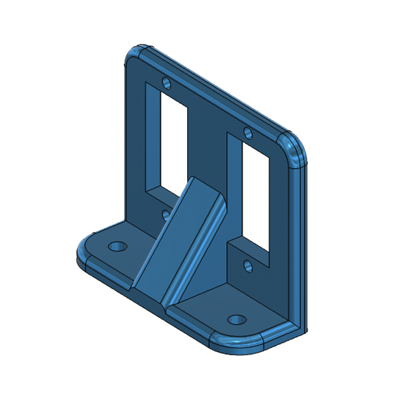 Servo Bracket
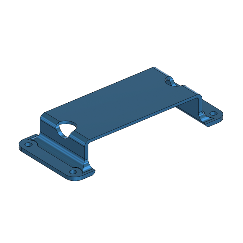 Battery Bracket
 Battery Compartment
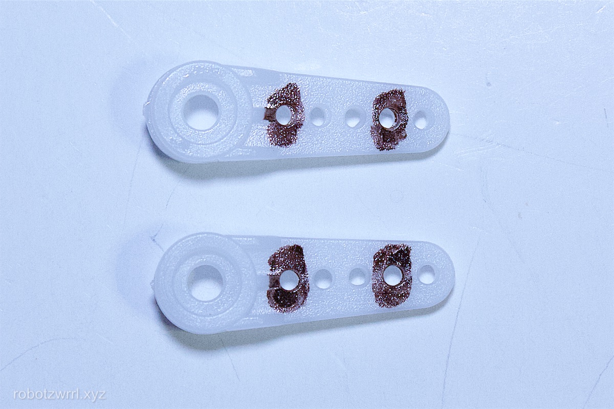
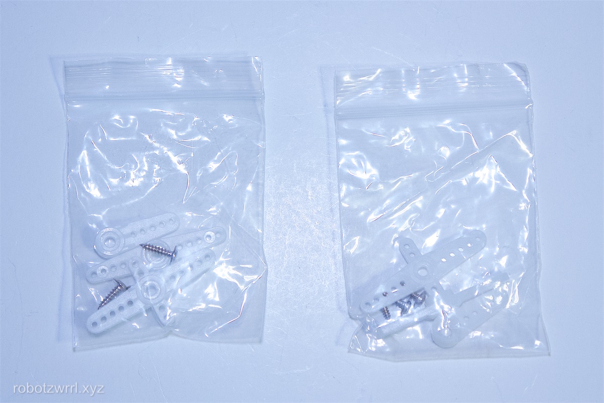
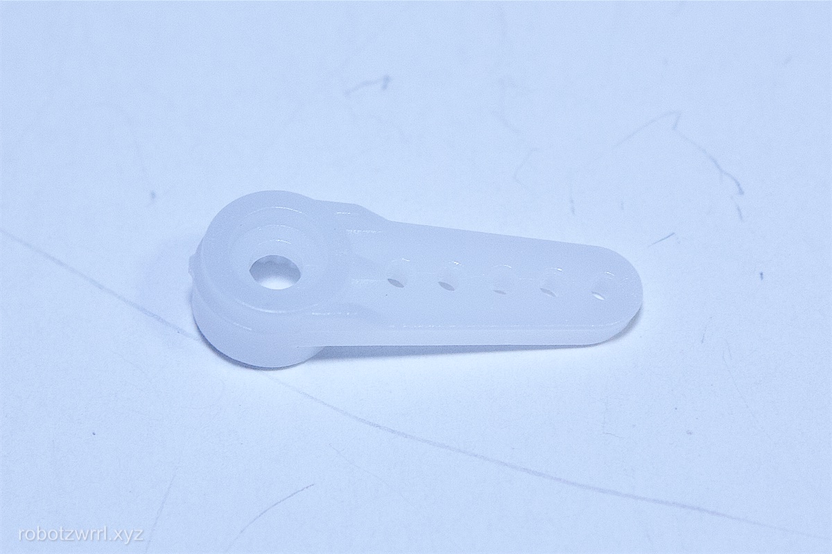
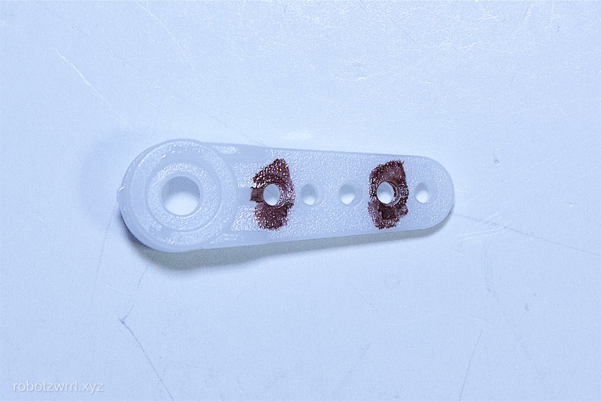
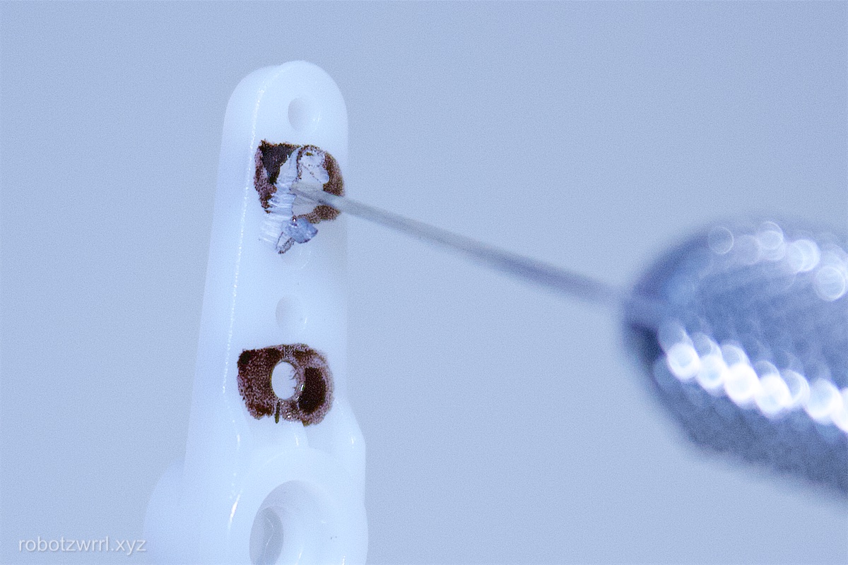
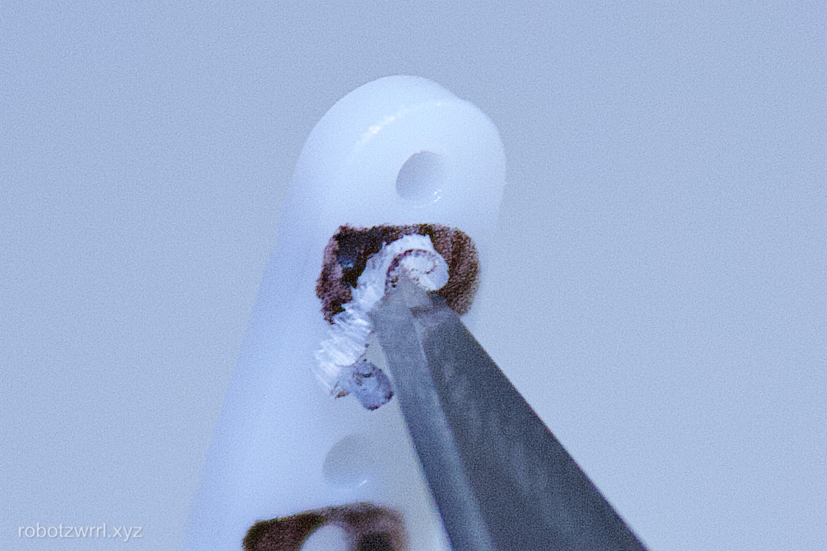
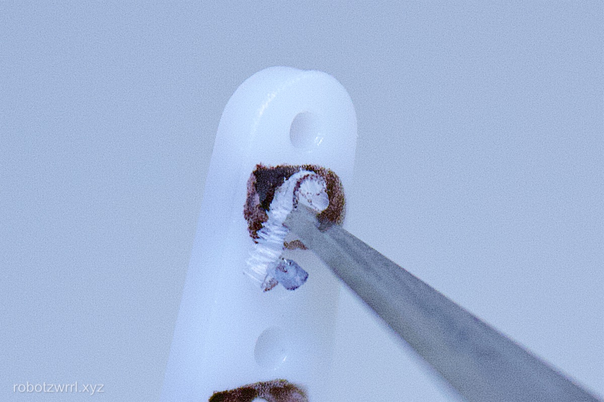
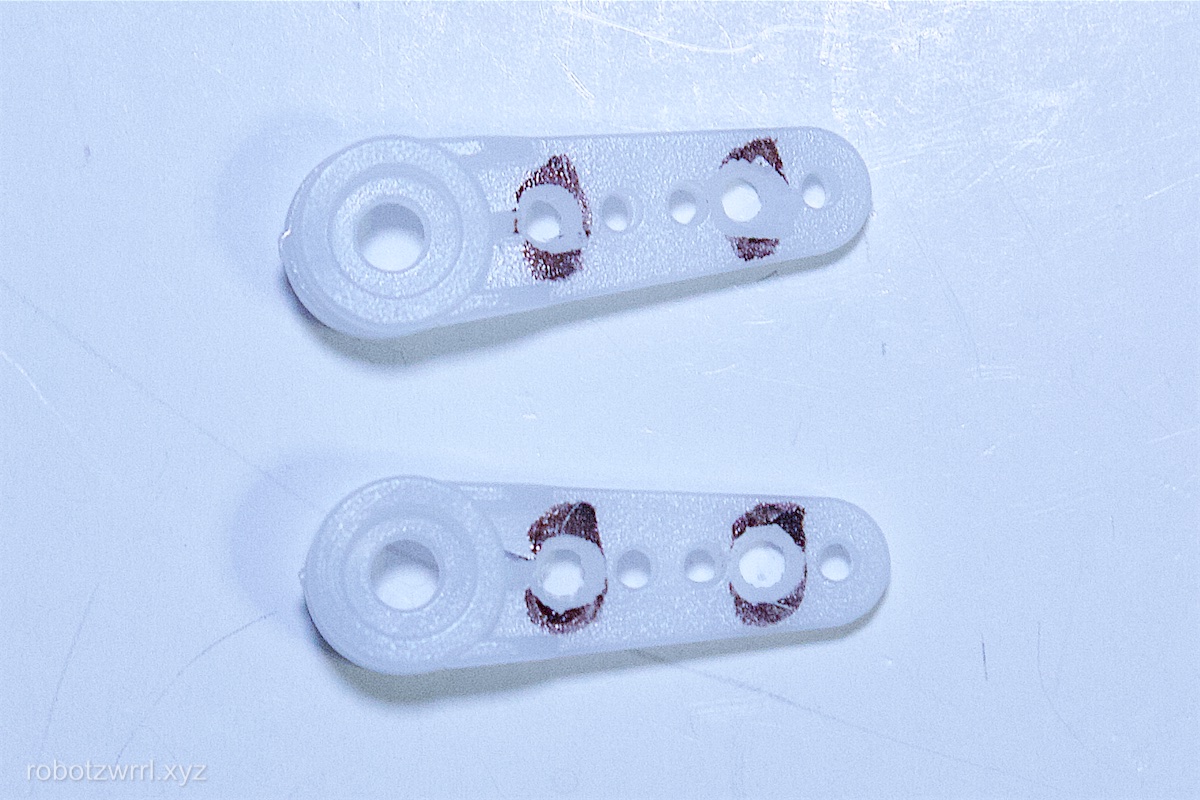
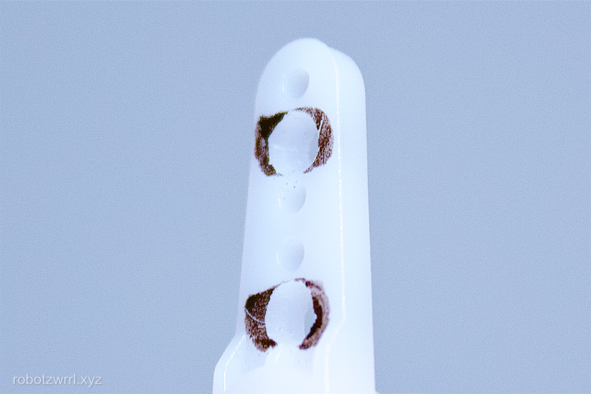
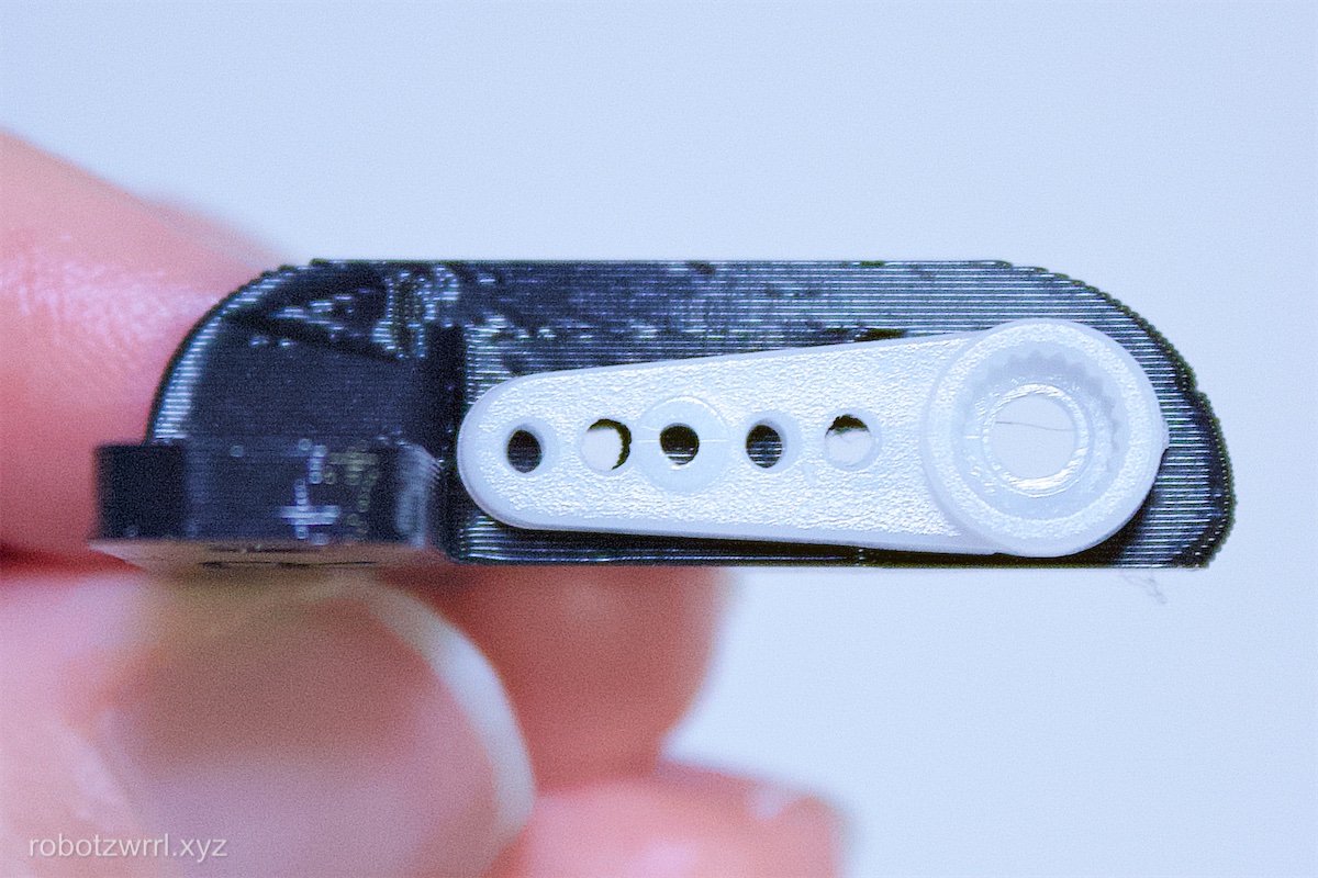
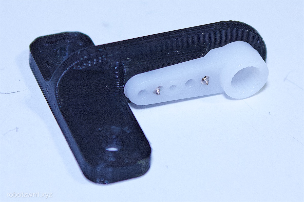
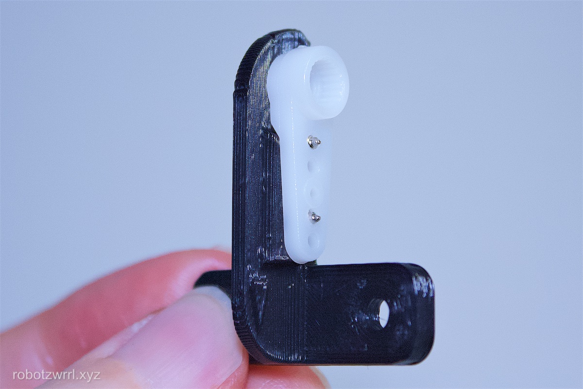
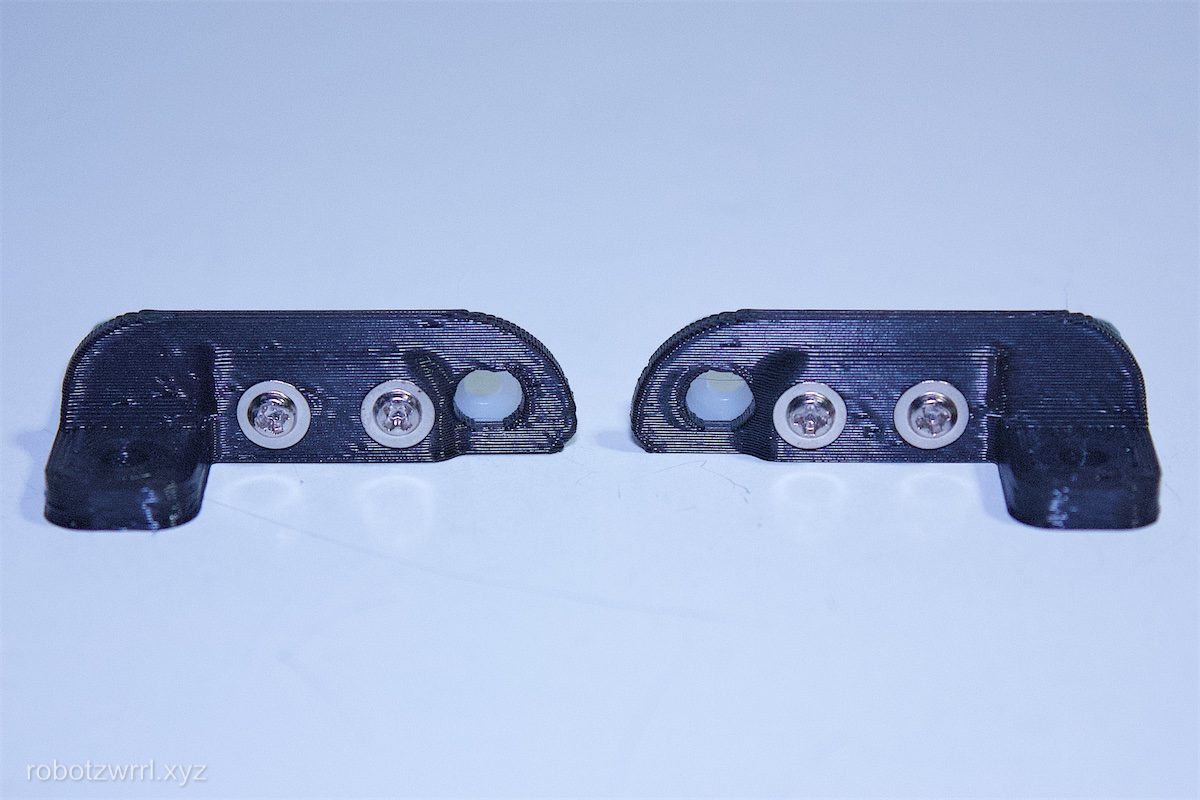
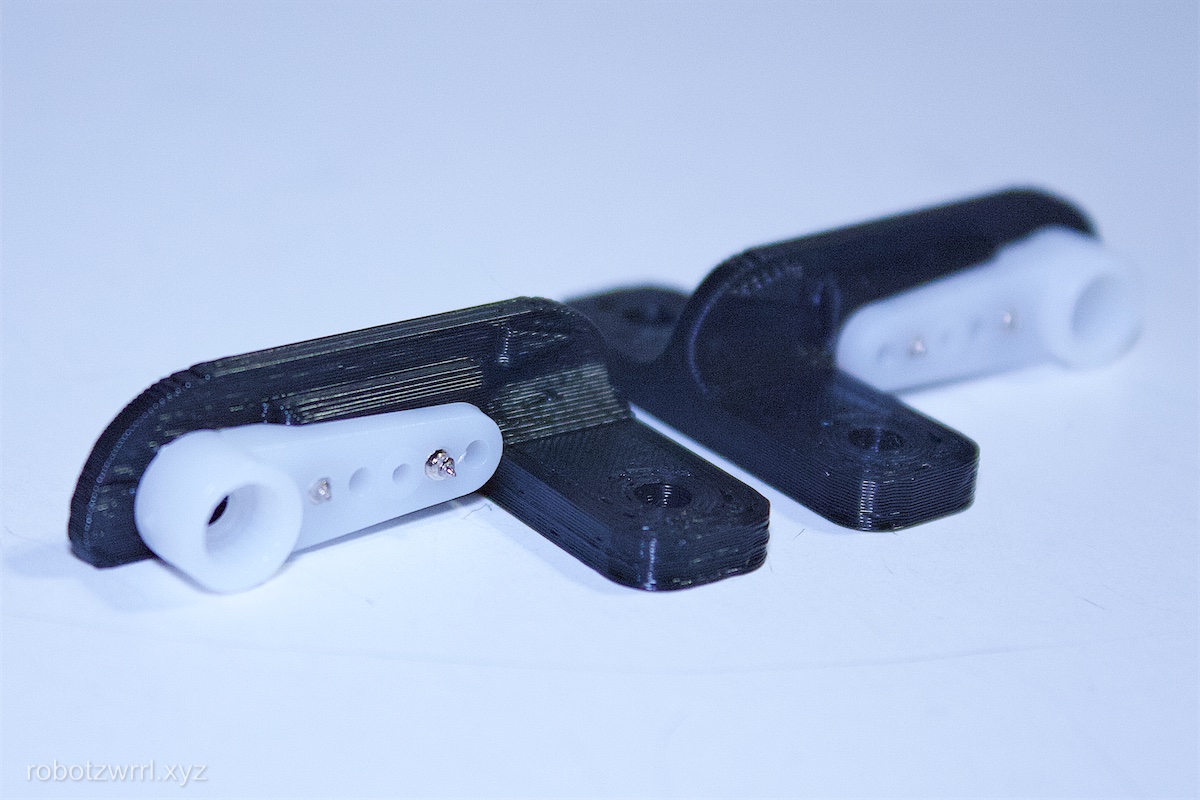
It’s time to prepare the servo horns. From the servo bag, find the white plastic servo arms that only extend in one direction. On the side that does not have the protrusion with the servo axel nub and splines, mark the first hole and the fourth hole on the servo horn using a permanent marker. Debur the edges of the marked holes with an Xacto knife to make a chamfer.
The purpose of this step is to prepare the servo horn so that it will sit flush with the 3D printed piece. When adding the fasteners through the white plastic servo horn without deburring, a buildup of plastic forms - which causes the seating to be uneven.
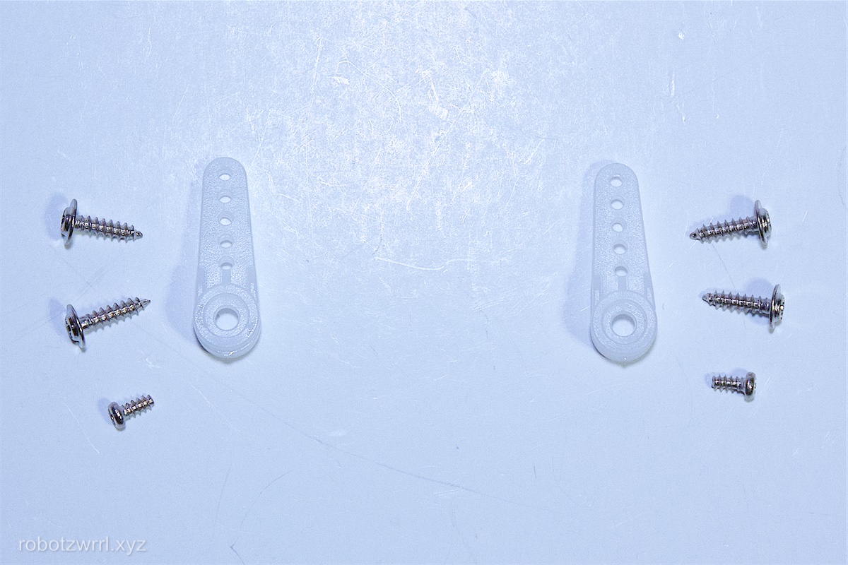
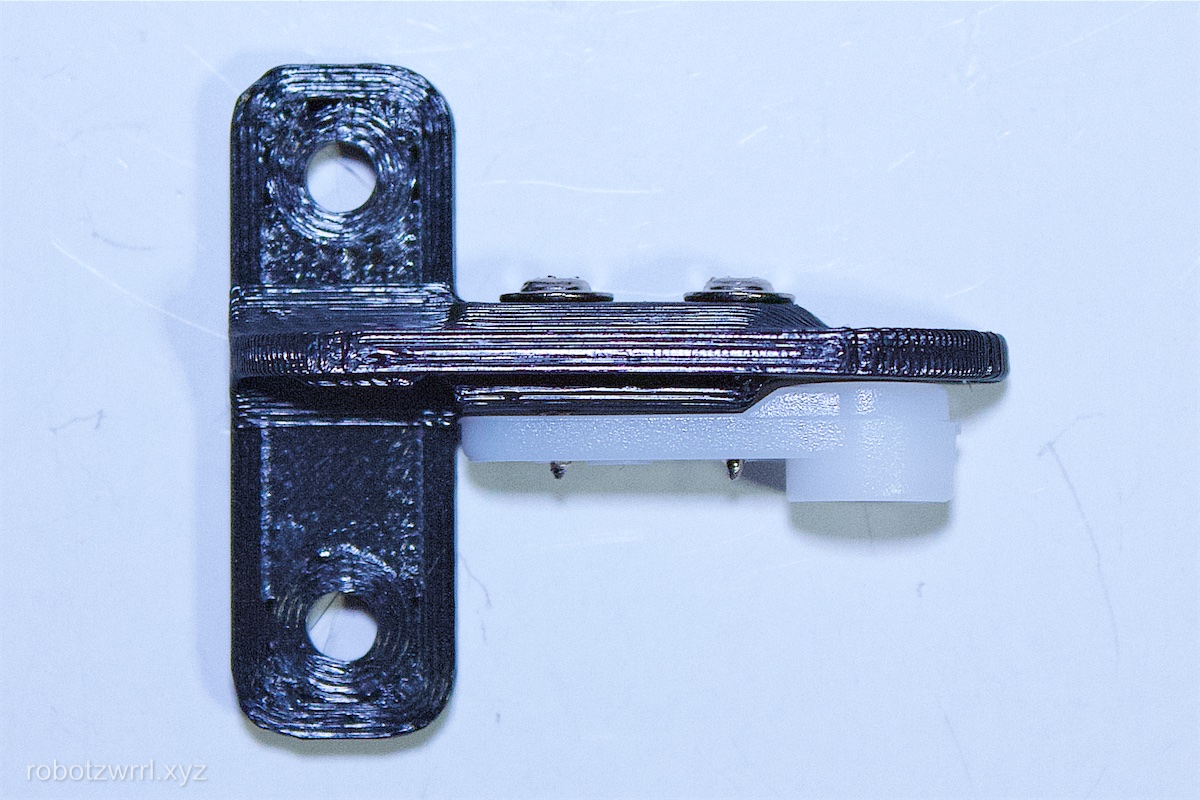
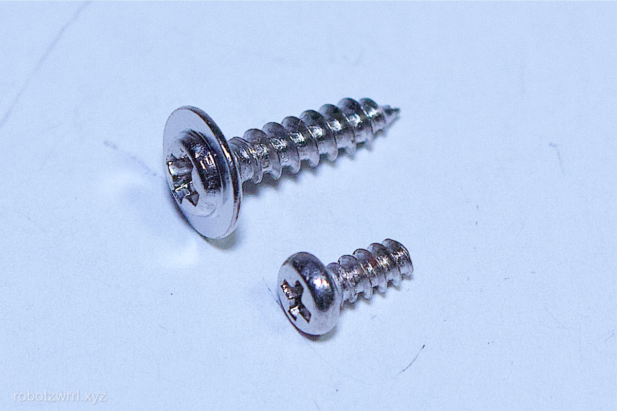
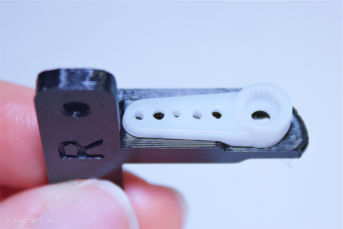
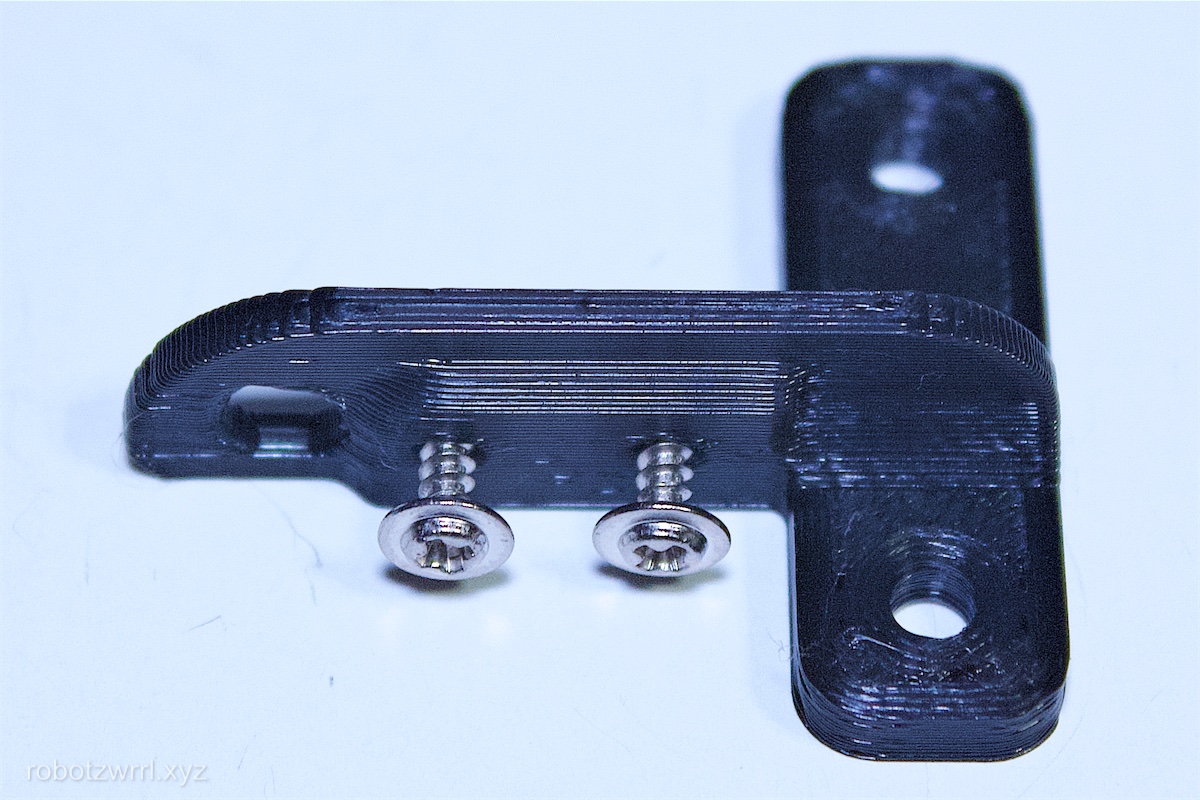
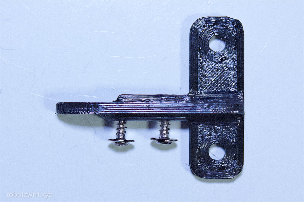
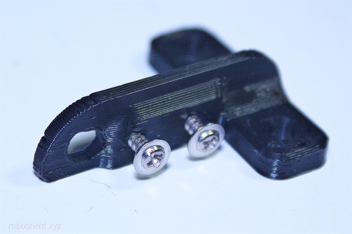
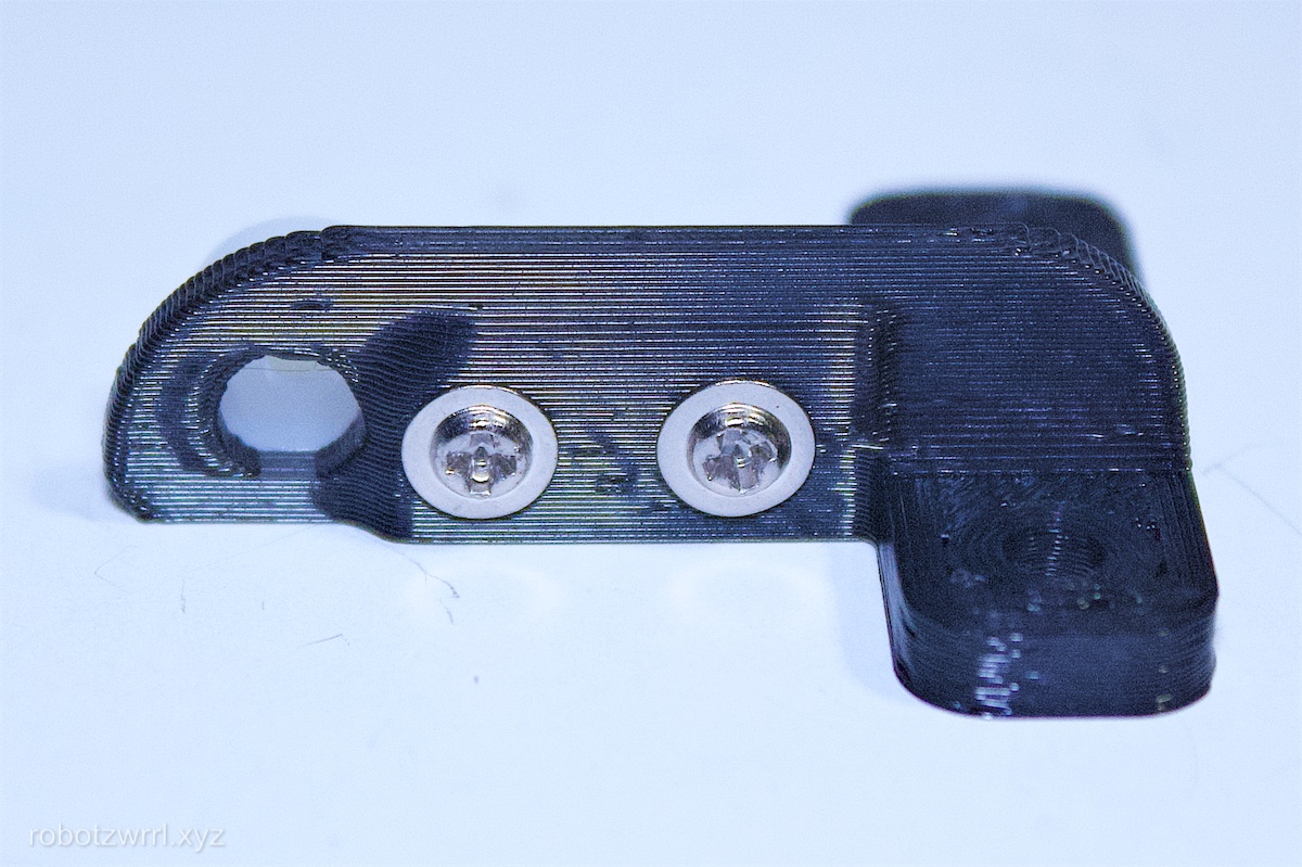
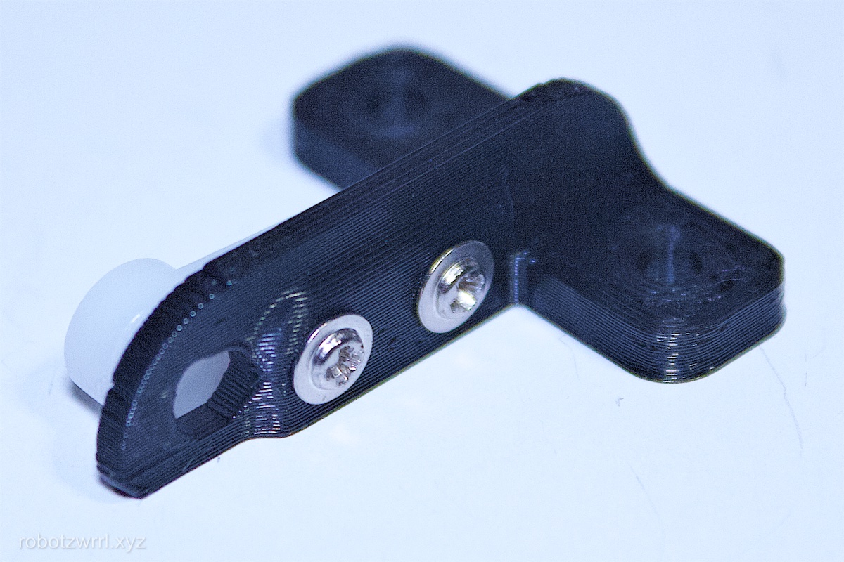
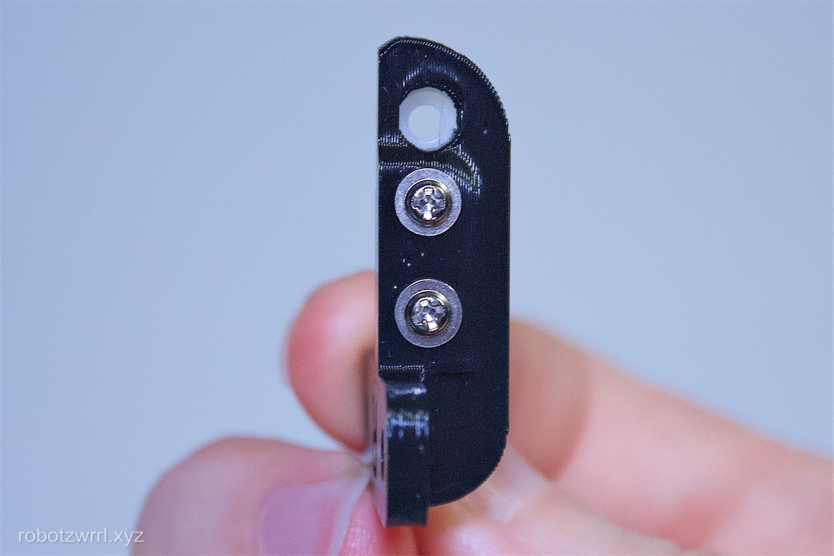
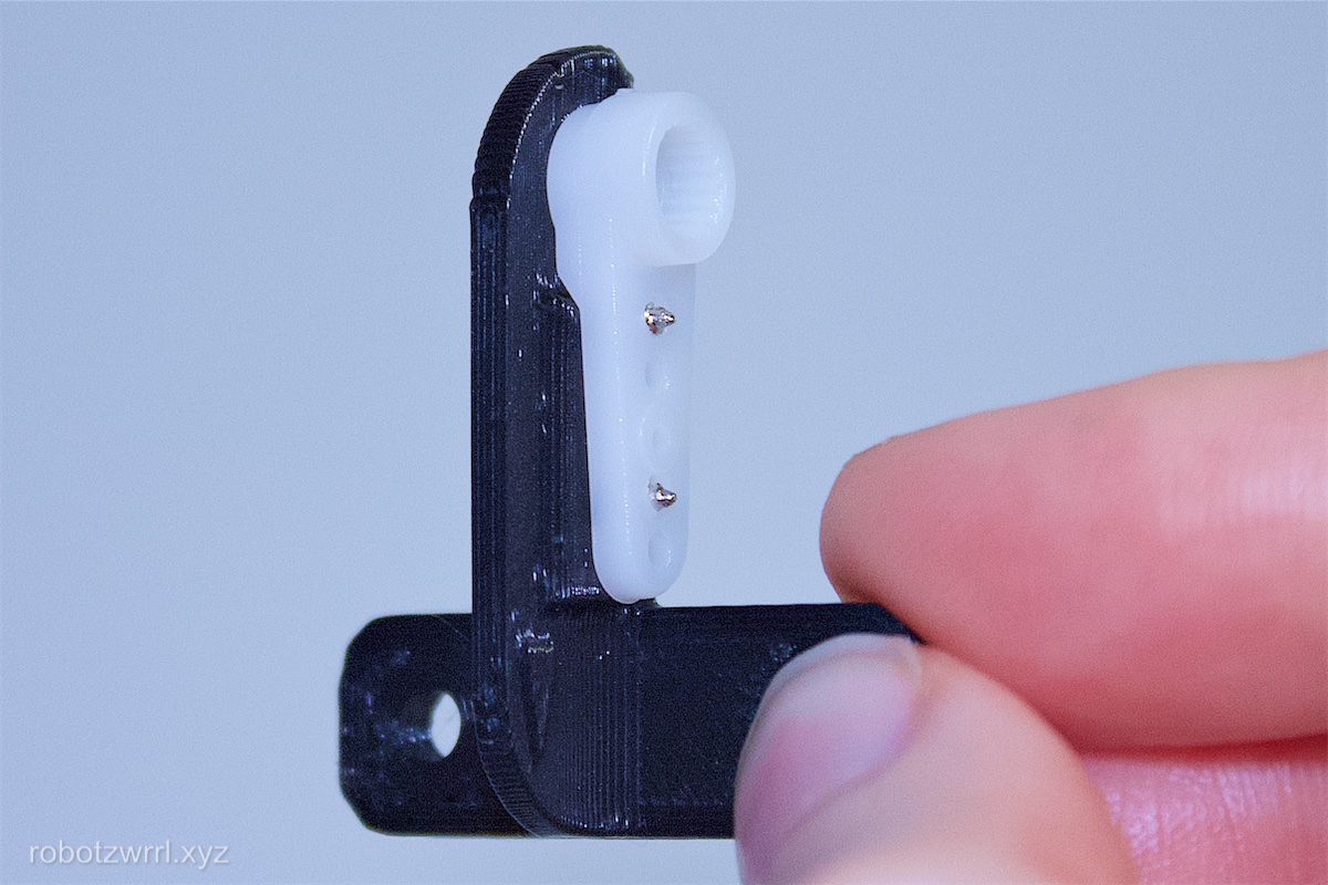
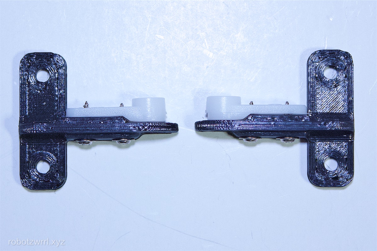
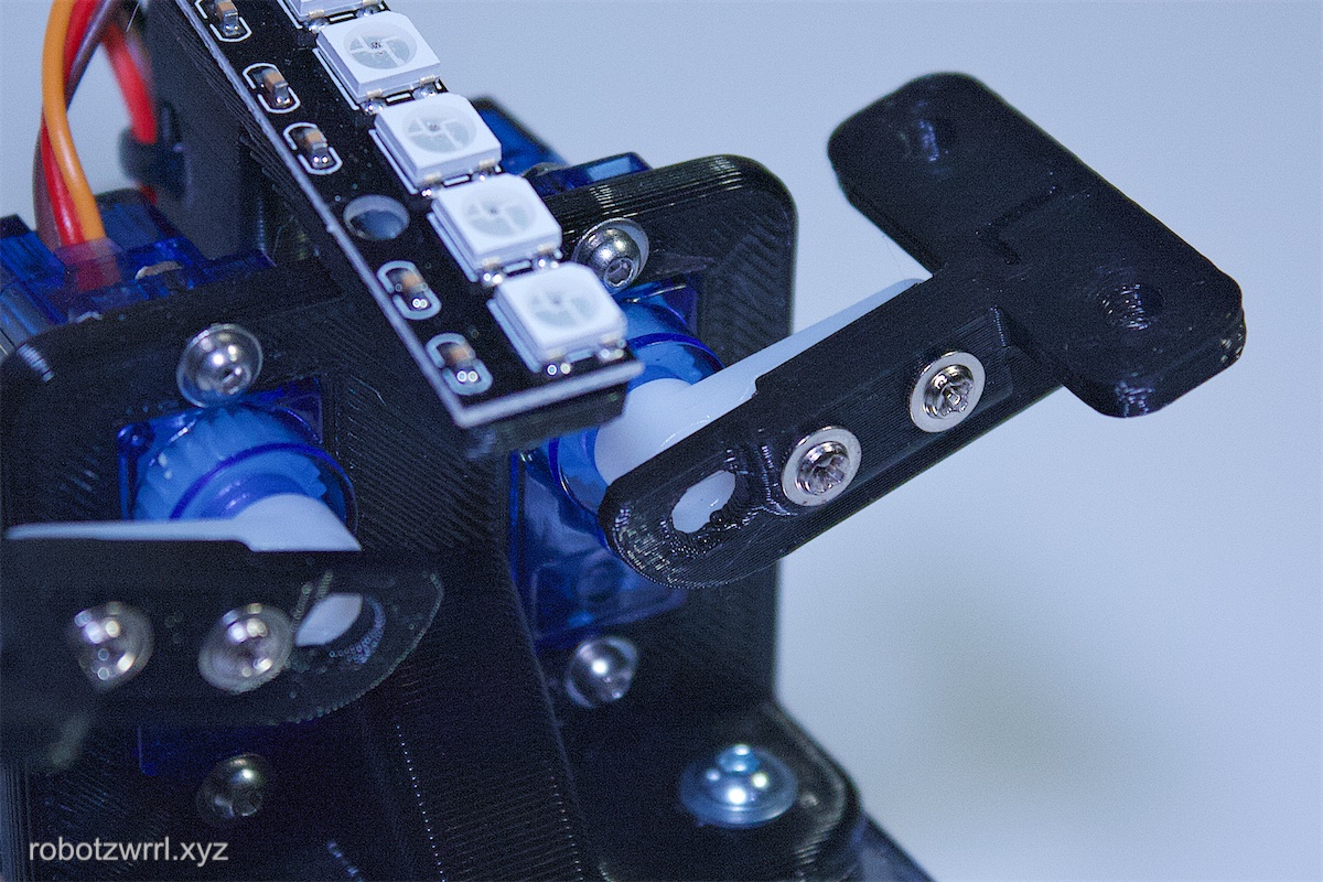
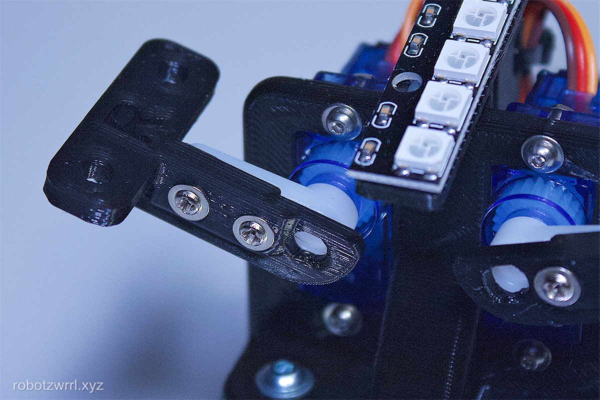
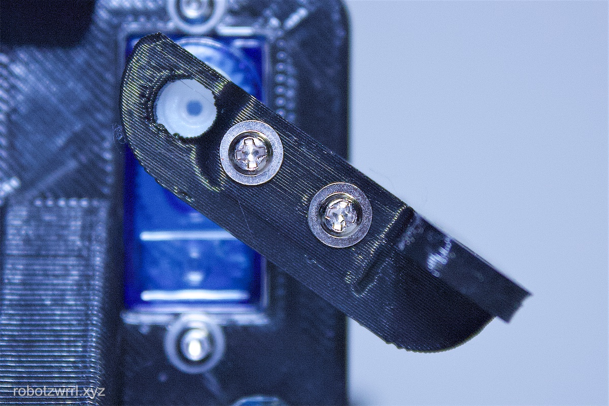
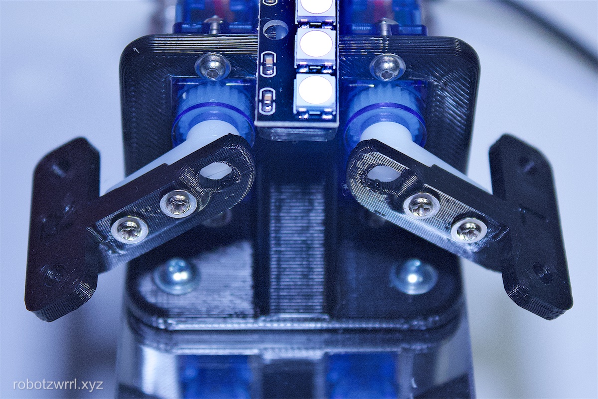
Fasten the servo arm to the 3D printed servo horn piece using the tiny wood screws in the servo bag. These wood screws have threads that extend outwards more than the other. The circle cutout on the 3D printed piece should align with the servo horn axel. The flat of the servo horn should be in contact with the side that has the triangle marking. The screws go through the 3D printed piece and through the chamfered holes from the previous step (the first hole and the fourth hole on the servo arm). Please refer to photos for clarification.
The purpose of this step is to retain the snug fit that the injection moulded white plastic servo horn has with the splines — while also having an interface to the butterfly wings.
Note: Set aside the servo horn axel screw for the time being as it will be used in an upcomming step.
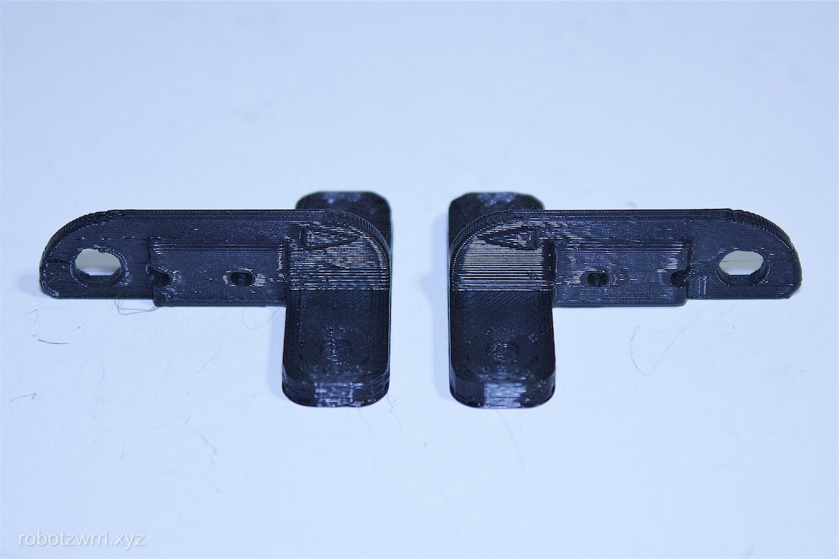
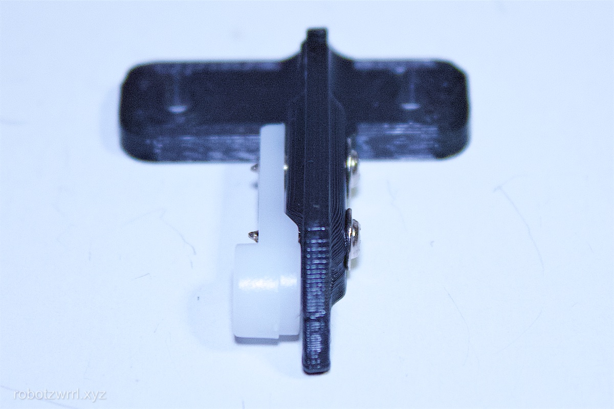
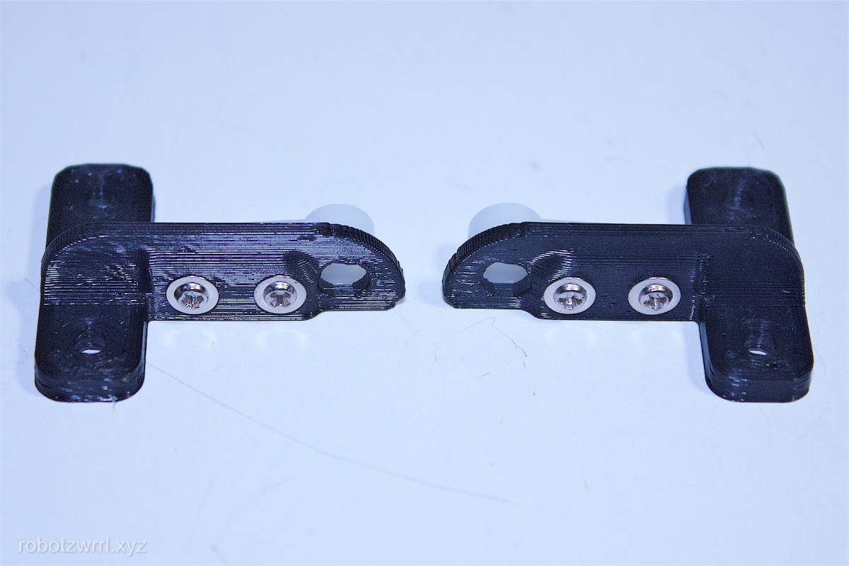
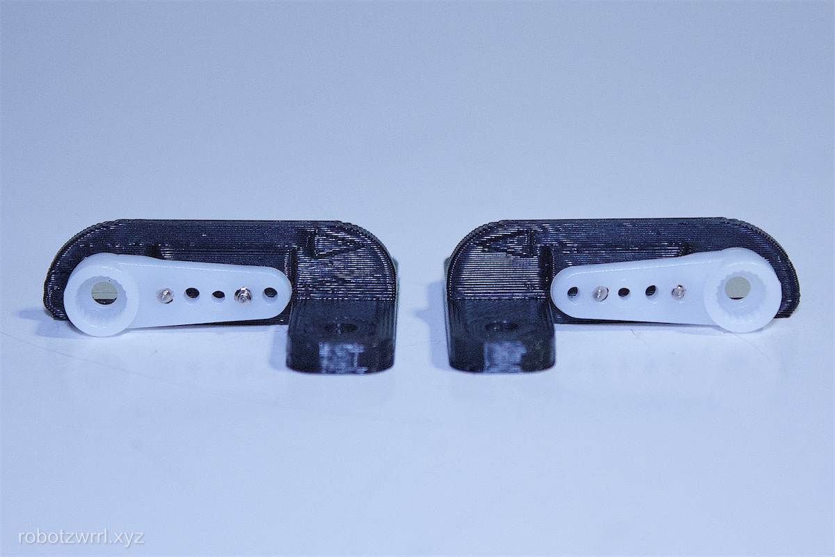
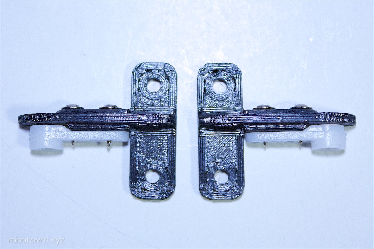
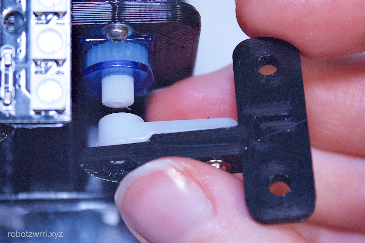
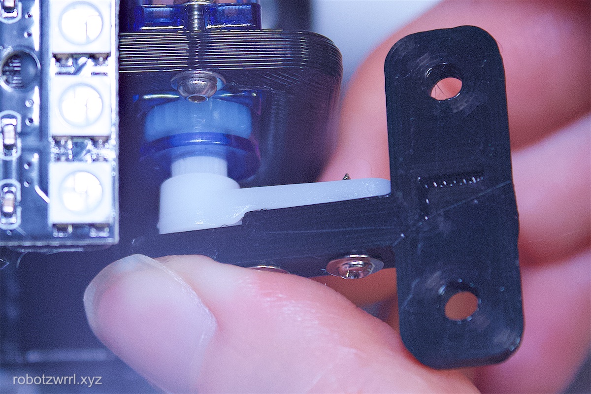
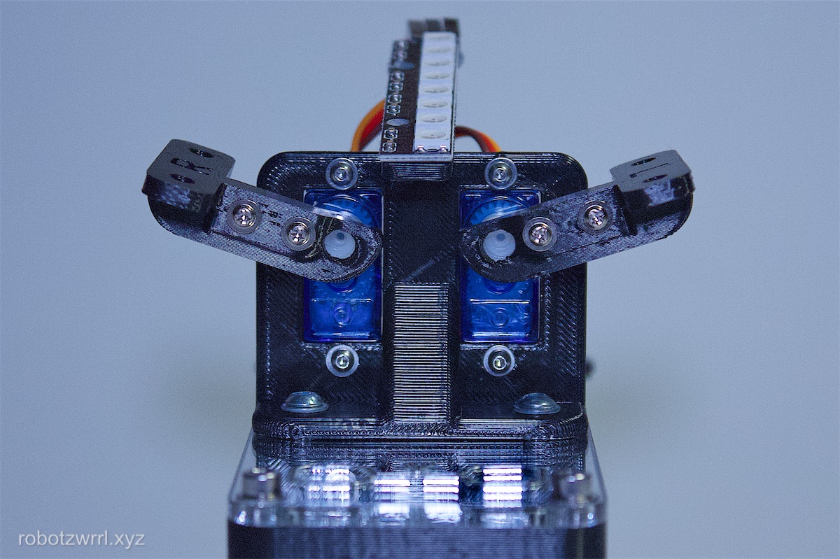
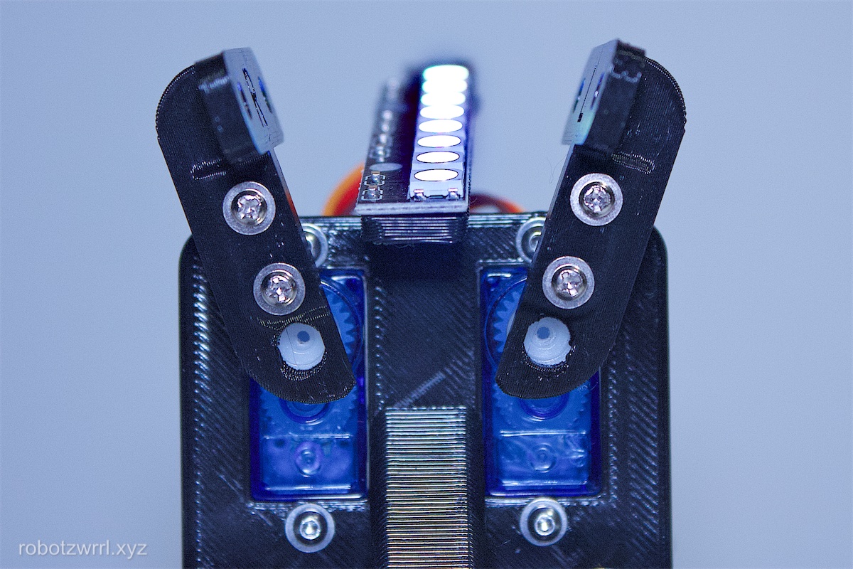
Press the 3D printed piece + servo horn onto each of the servo axel splines. The smooth side of the 3D printed pieces face inwards towards the Neopixel mount. The splines on the axel and horn have to align in order to attach. If it does not attach at first, try rotating the servo horn very slightly. The positioning will be dialed in further in an upcomming step.
The purpose for this step is to gain familiarity with attaching the servo horn, as the next step will involve more precise positioning of this piece.

Note: This instruction step assumes Robot Butterfly is running the latest version of the firmware. It's possible an update may be required.
Power on the robot. Within the first 30 seconds, press and hold the two buttons at the same time. Wait until you hear a "beep ... beep ... beep" sound. Release the two buttons. You will now see two of the Neopixels as a green colour, this means the robot is in servo calibration mode.
The servos start in the up position. Pressing the left button will cycle the left servo position from up to home to down and then back again. Same thing for pressing the right button and the right servo.
Press the buttons accordingly so the servos have moved to their upright positions.
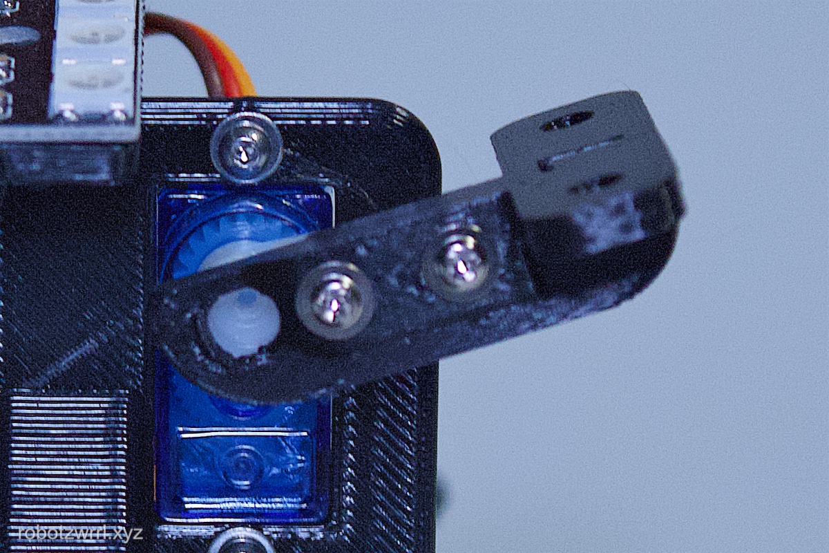
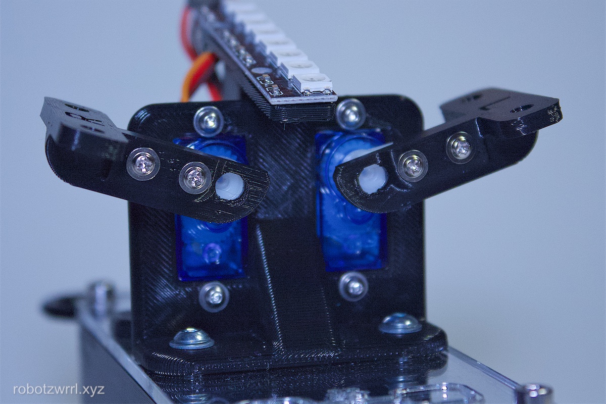
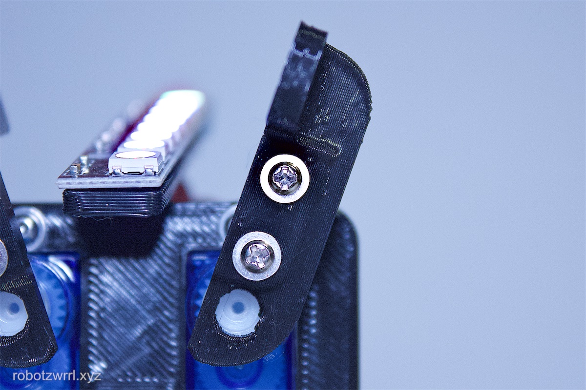
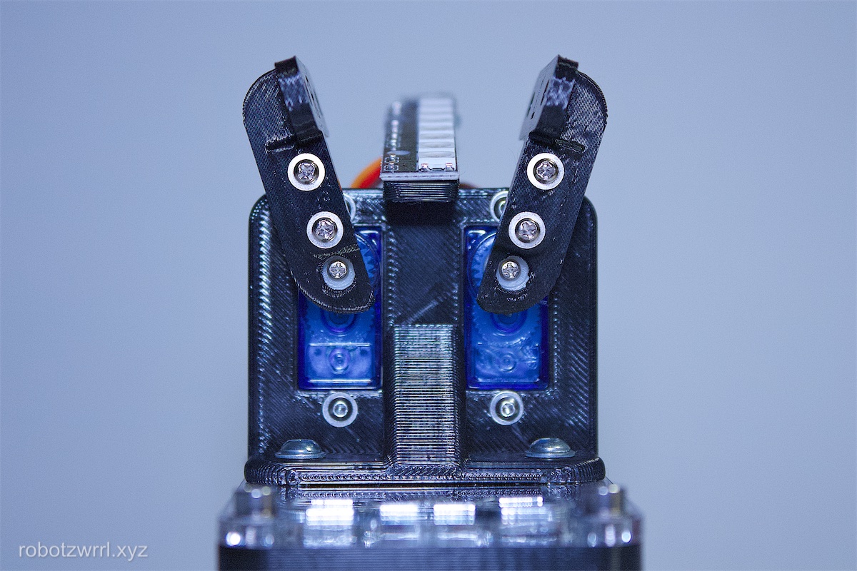
Finesse the position the servo horns by removing it from the splines and adjusting it and attaching it back to the splines. The position should be such that the servo horns are 10 degrees away from being perpendicular to the lid. Ensure the servo horns do not collide with the Neopixel mount. See photo for reference.
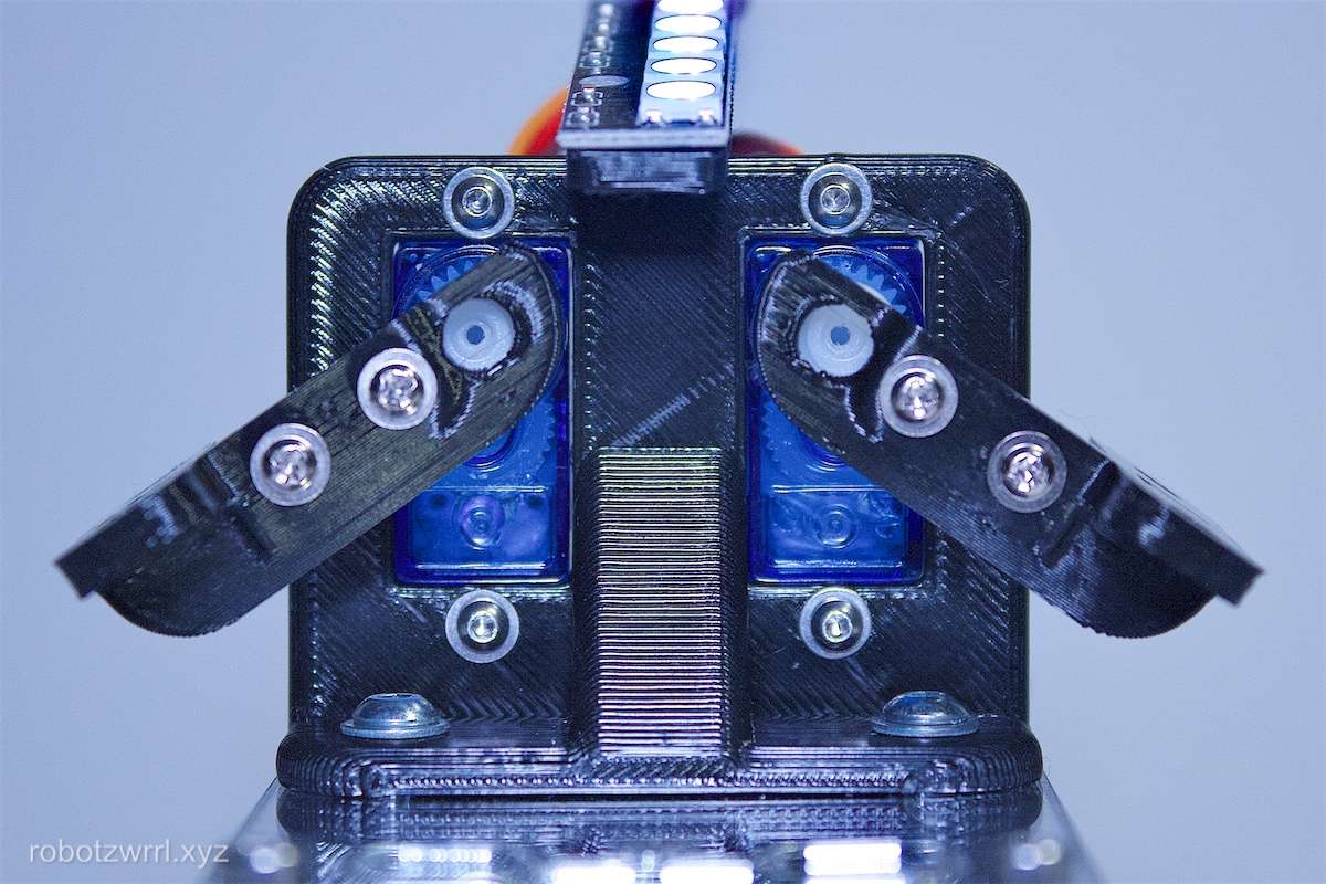
Now, in the same servo calibration mode, press the buttons accordingly so the servos have moved to their downwards positions.
Ensure that the servo arms do not collide with the Neopixel mount or the lid. Try to get both sides as symmetrical as possible, however, sometimes it might be off by about 5 degrees.
Repeat these two steps until there are no collisions and both sides are approximately symmetrical.
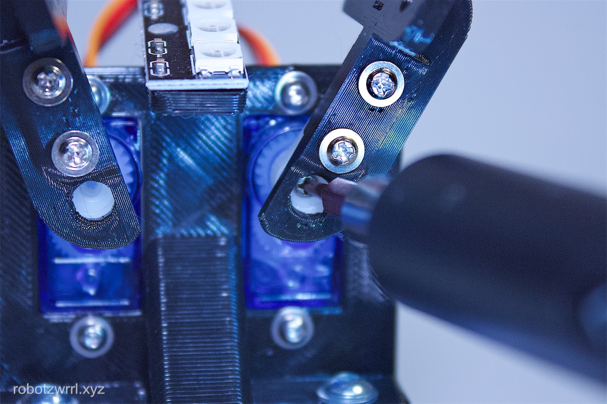
Once the positioning is correct, fasten the servo horn axel screws through the servo arm into the servo motor.
When you are done with the servo calibration, press and hold the two buttons at the same time. Wait until you hear a "beep ... beep ... beep" sound. Release the two buttons. Now Robot Butterfly is back to its regular state machine mode.
Page last updated: April 28 2025 11:04:08.