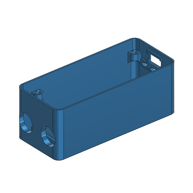
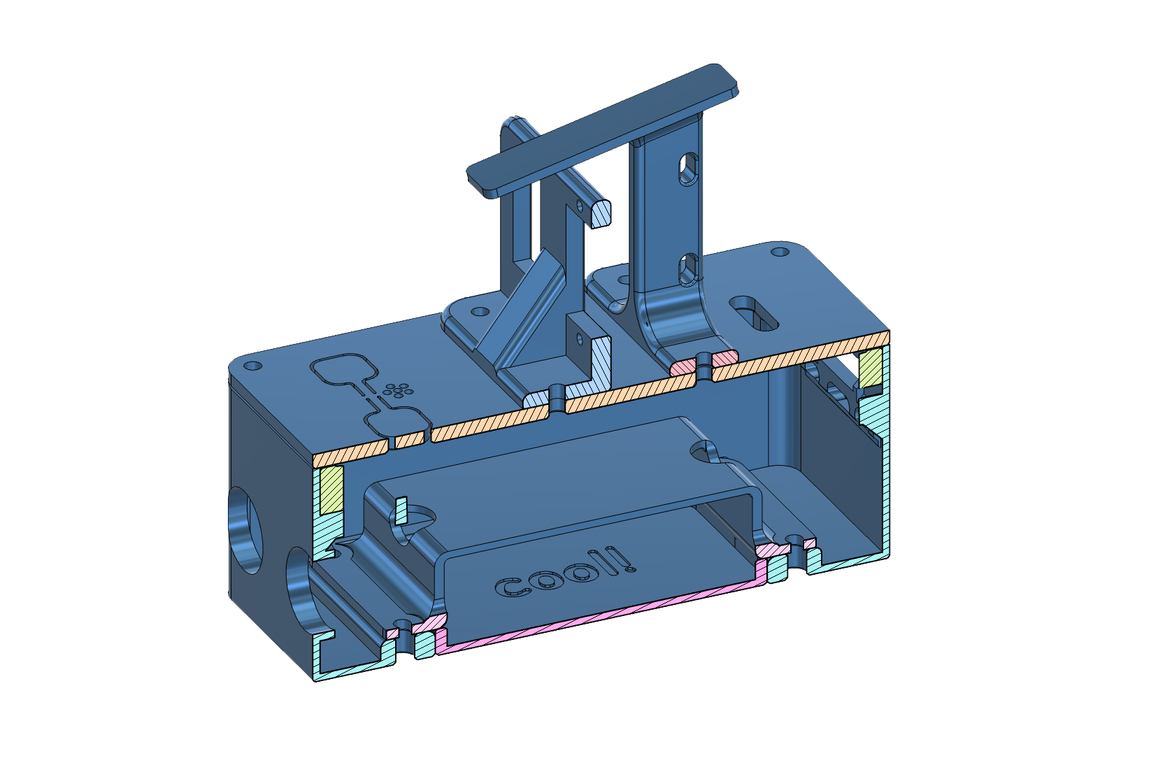
 Enclosure
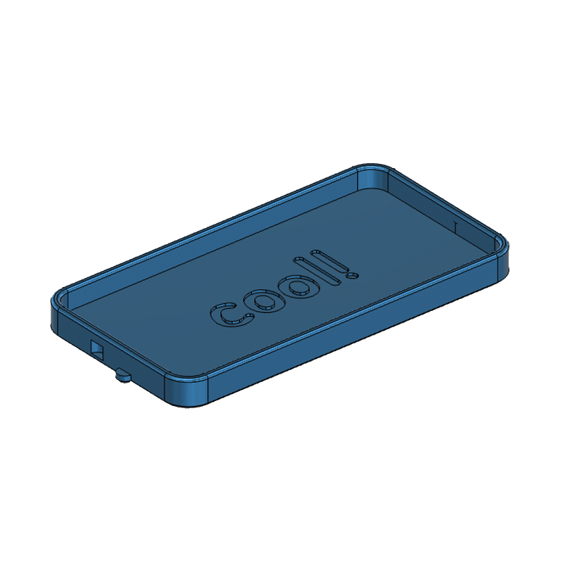
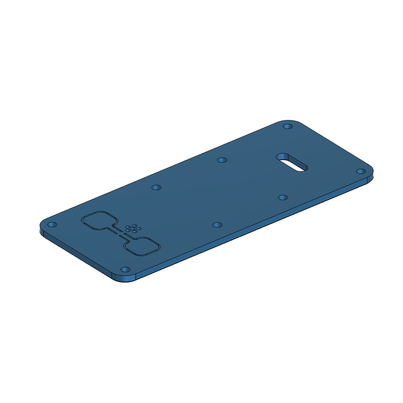 Lid
Lid
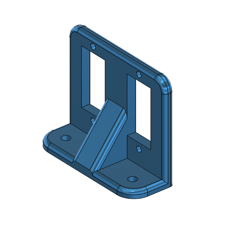 Servo Bracket
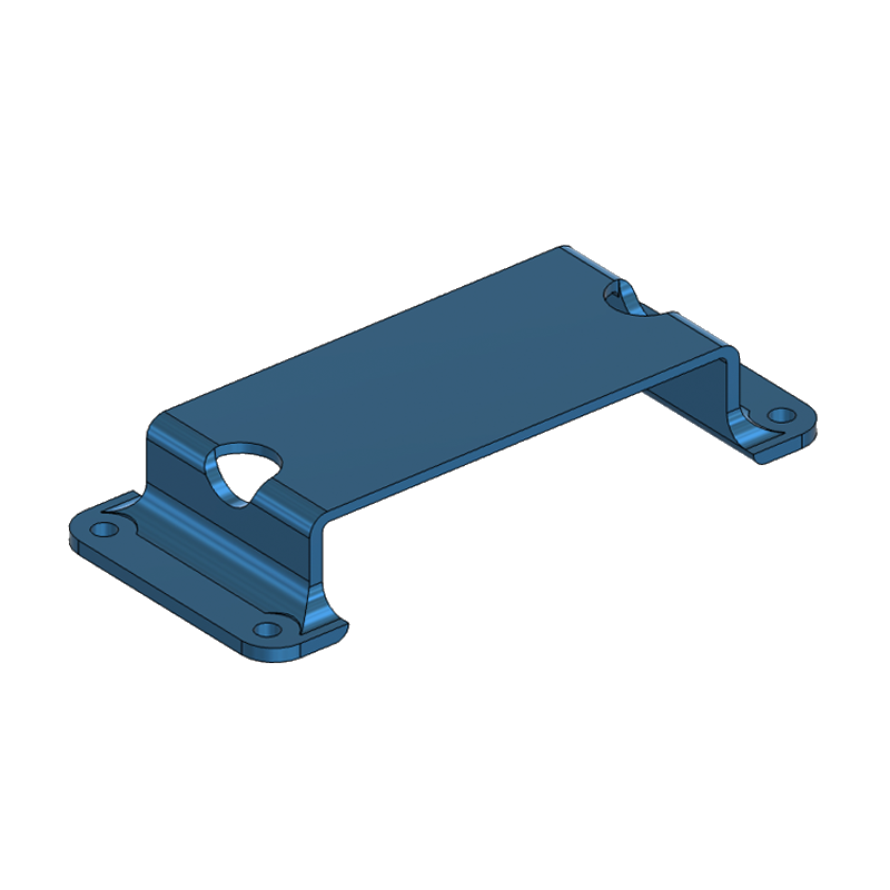 Battery Bracket
 Battery Compartment
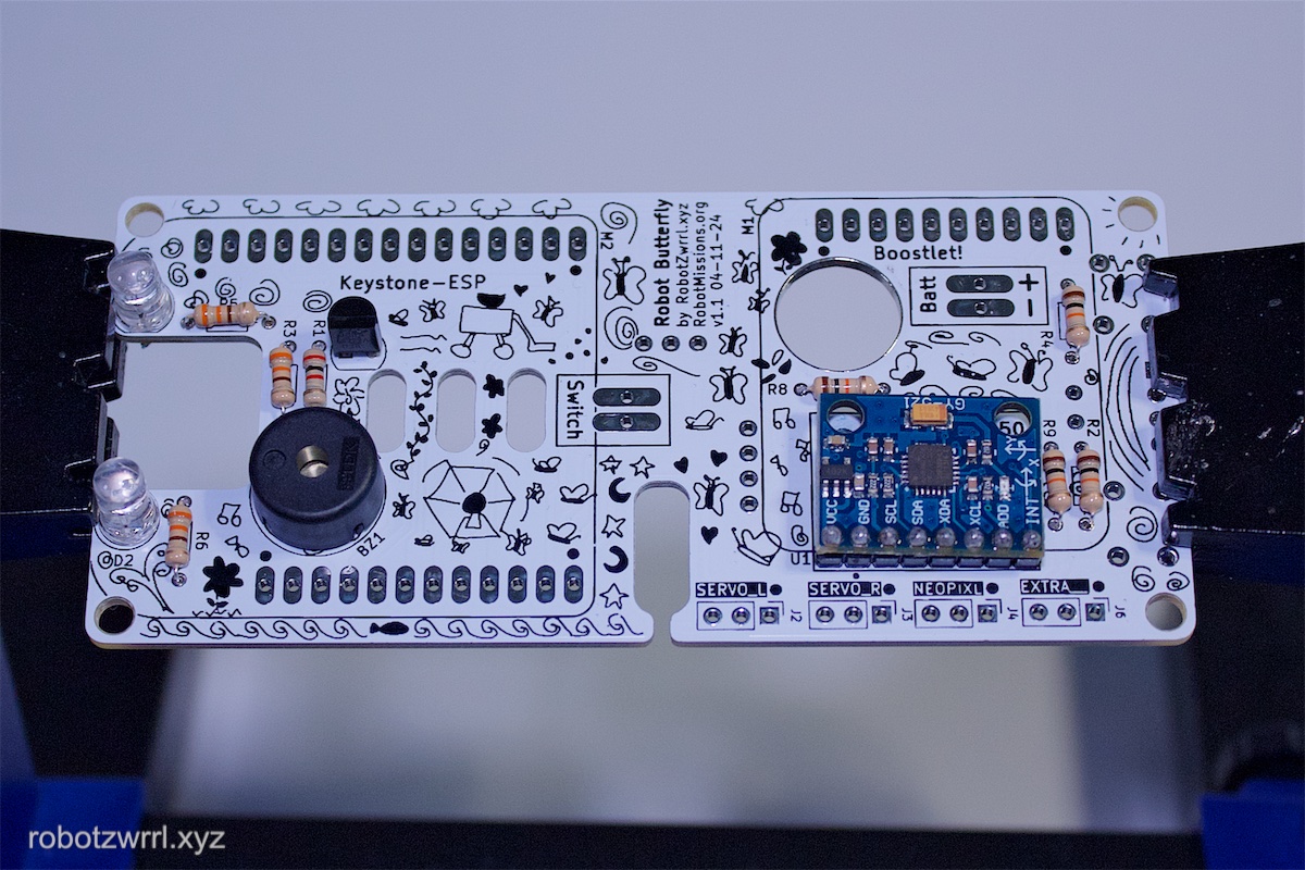
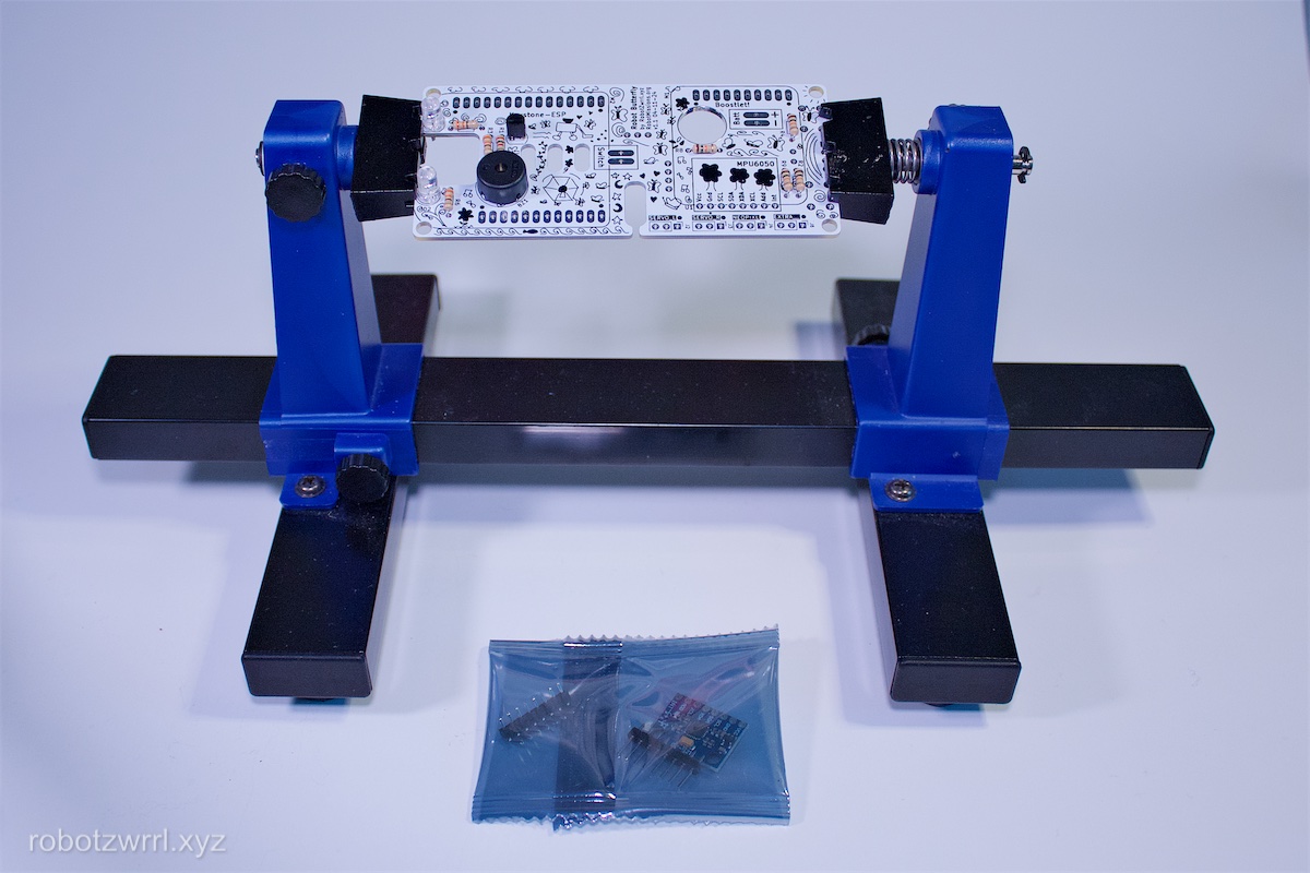
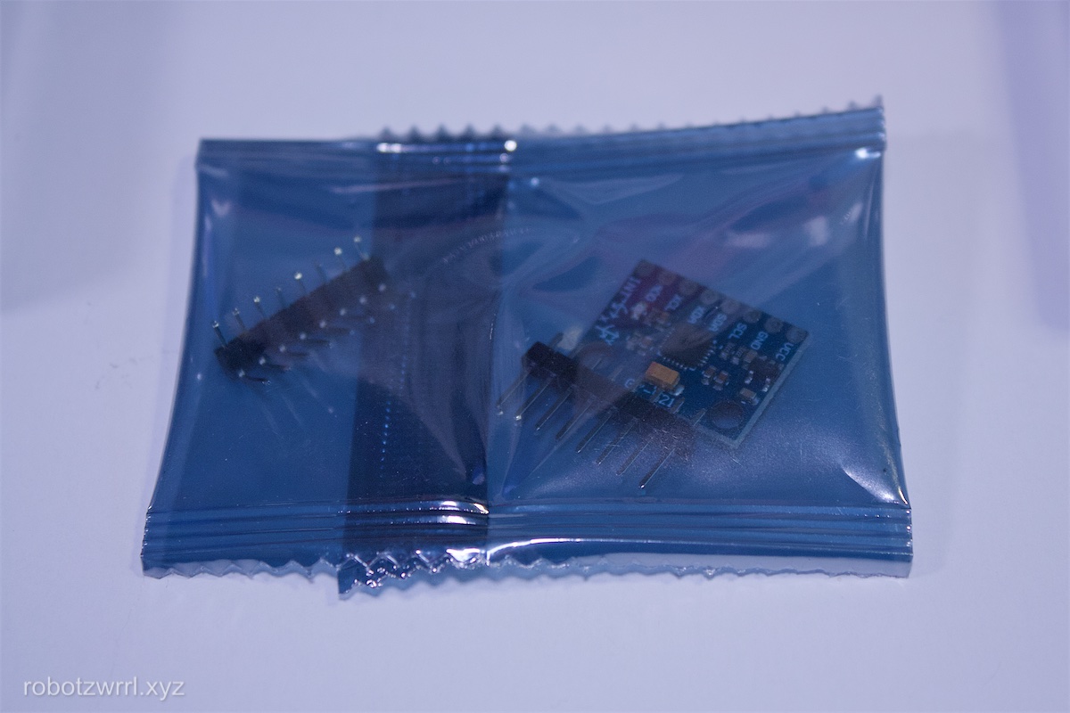
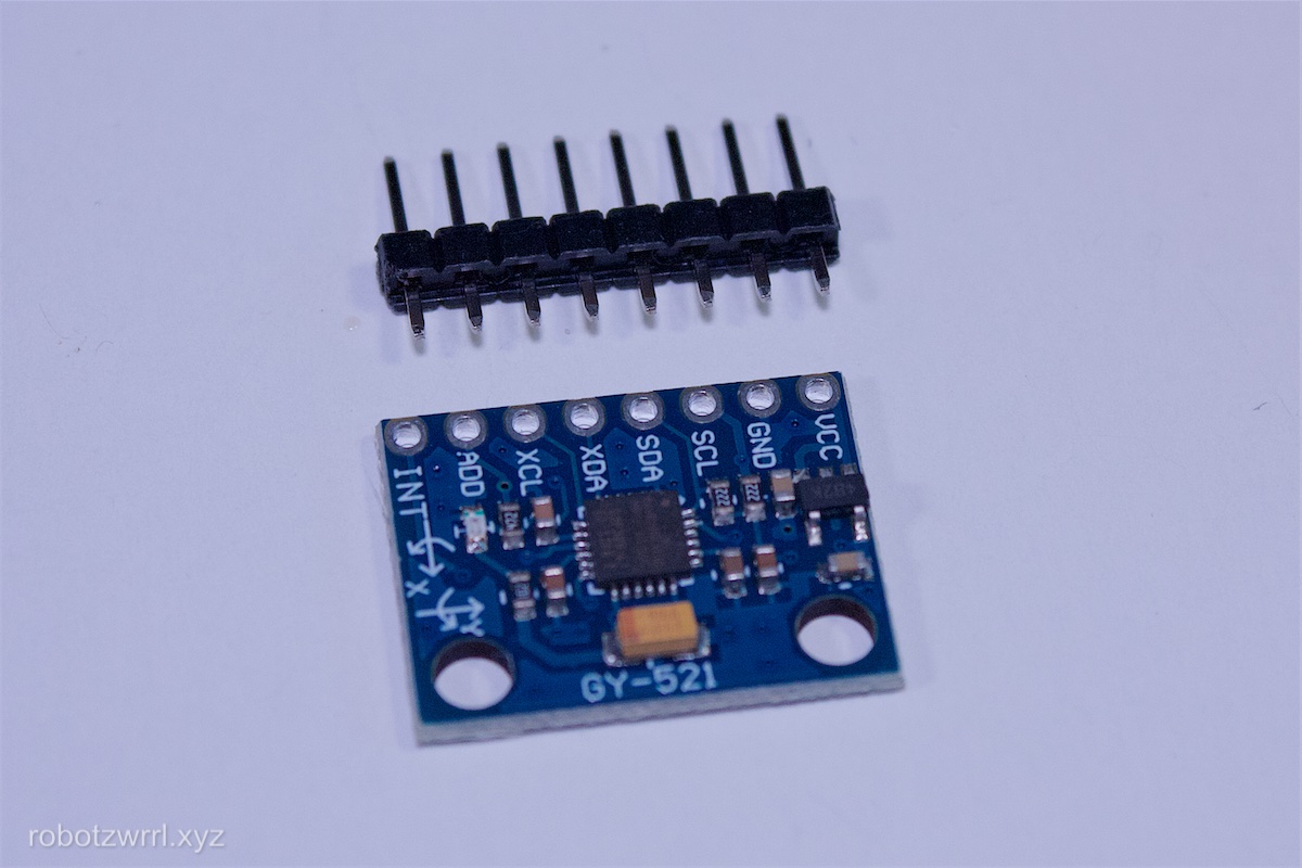
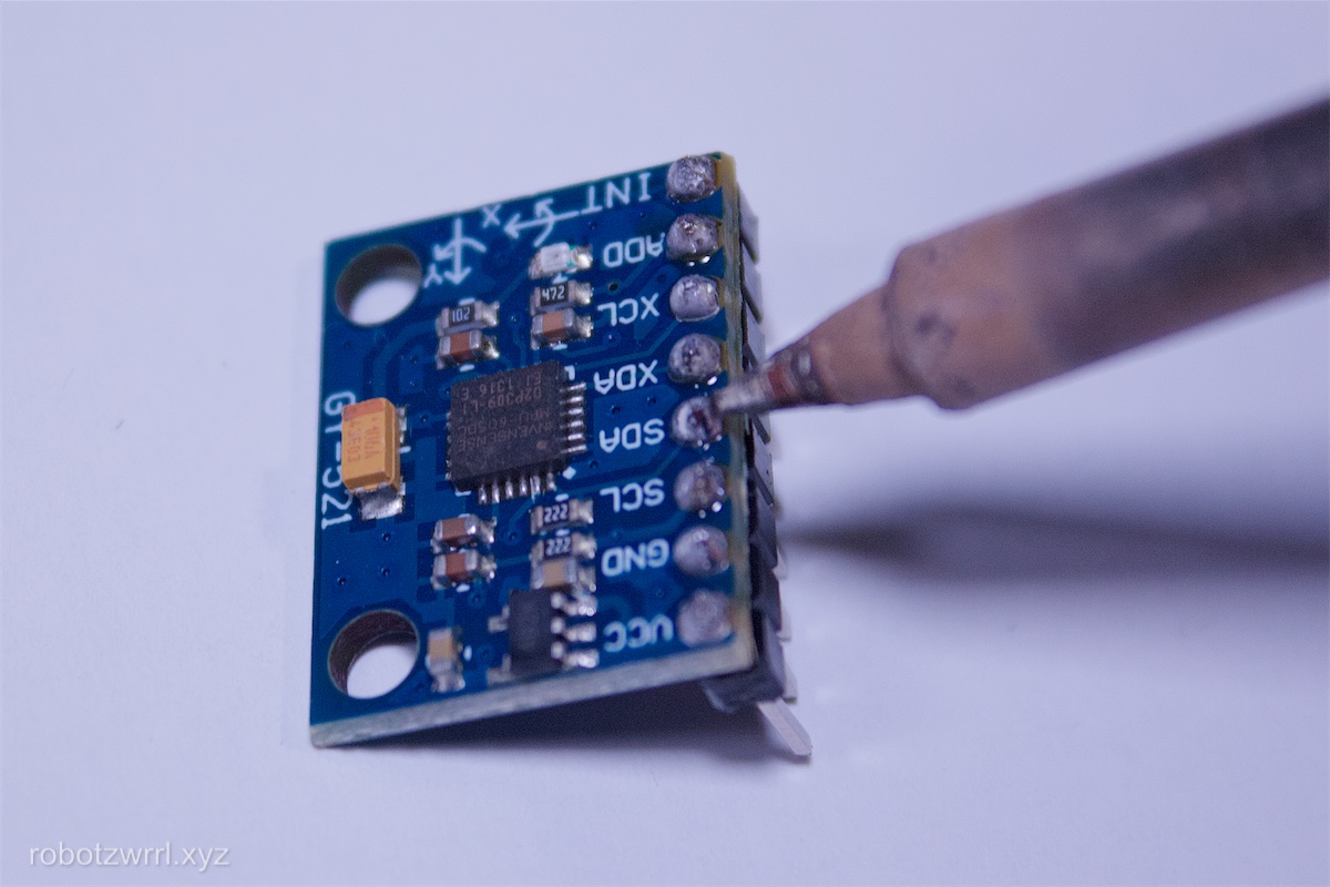
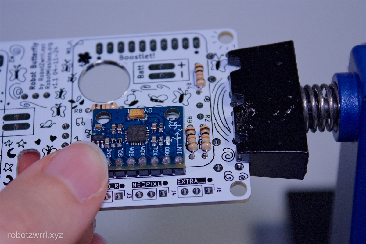
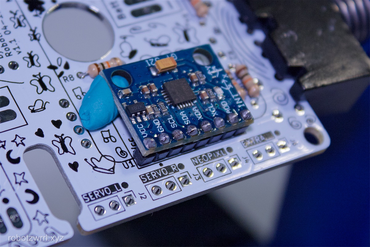
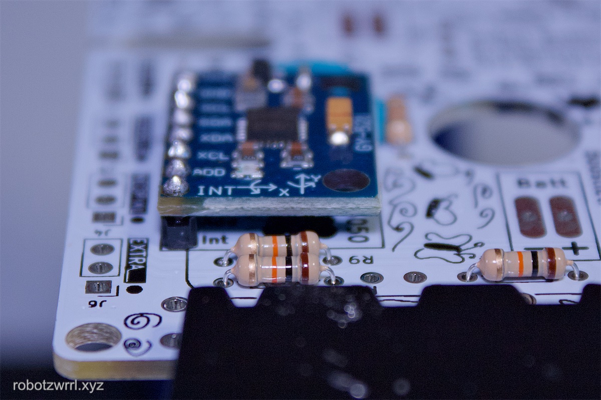
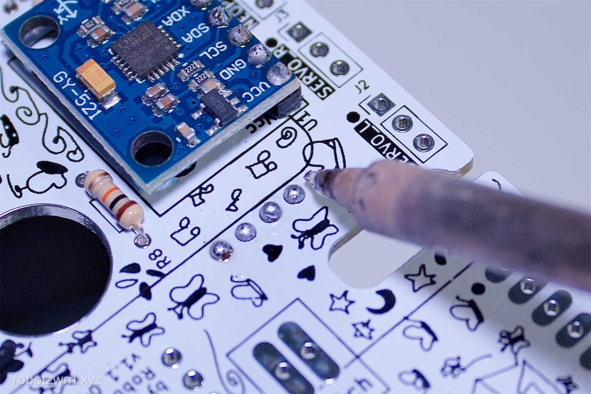
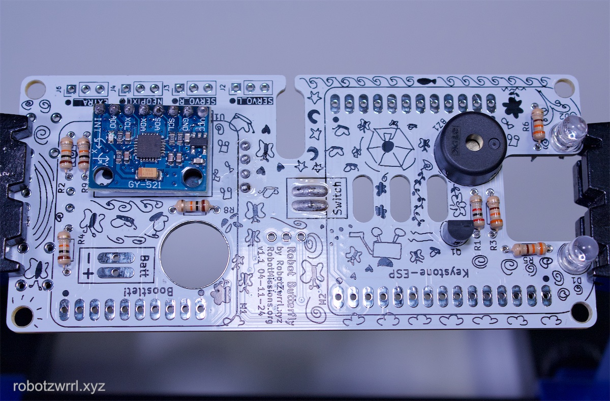
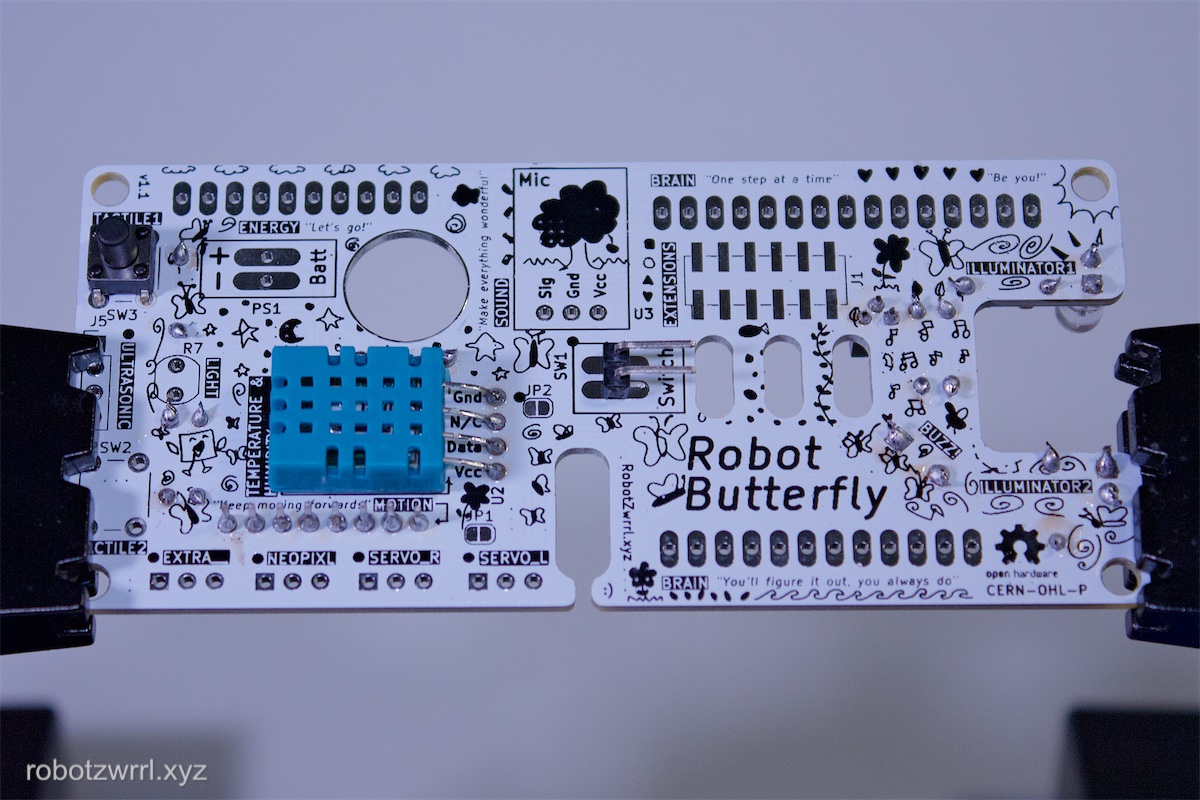
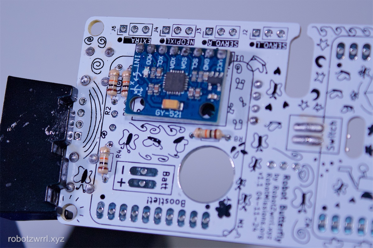
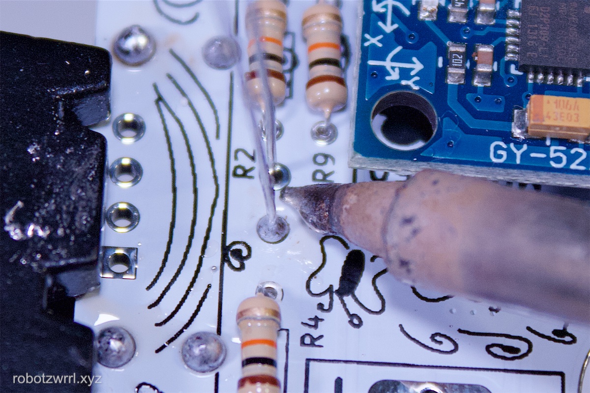
Solder the Inertial Measurement Unit (aka IMU), known as the part MPU6050. This goes into spot U1. The IMU’s breakout board may need its headers soldered to it as well. The breakout board should be facing up. Sticky tack can be used to help keep the position of the breakout board perpendicular. Please refer to photos for clarification.
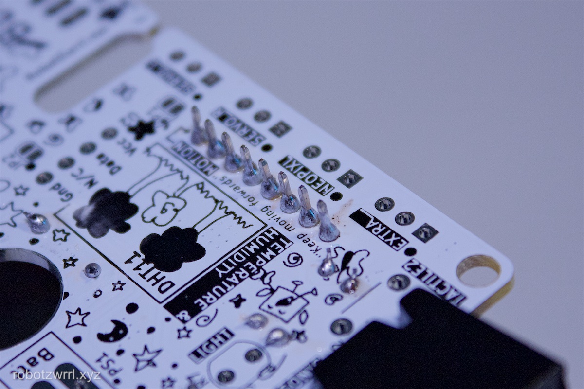
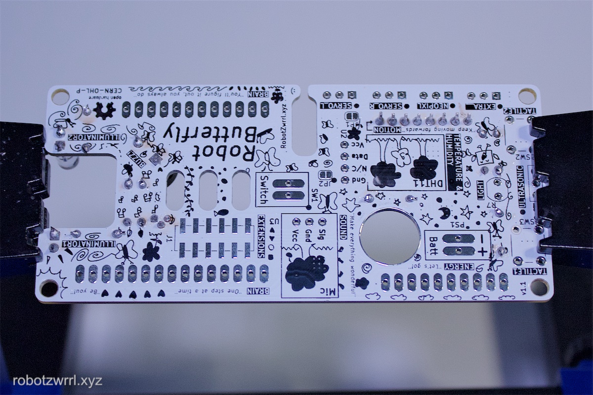
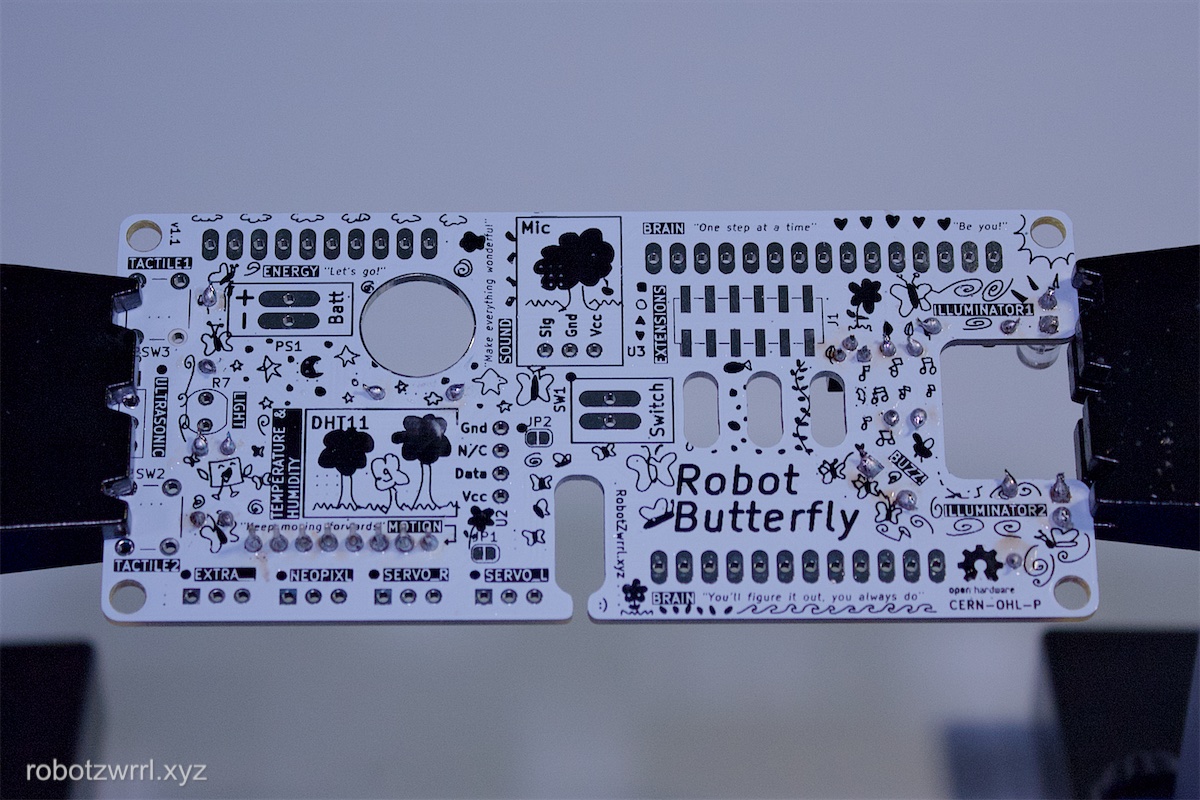
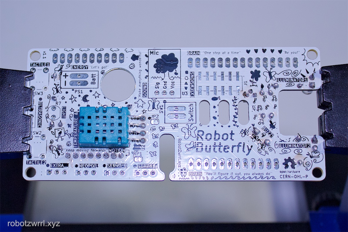
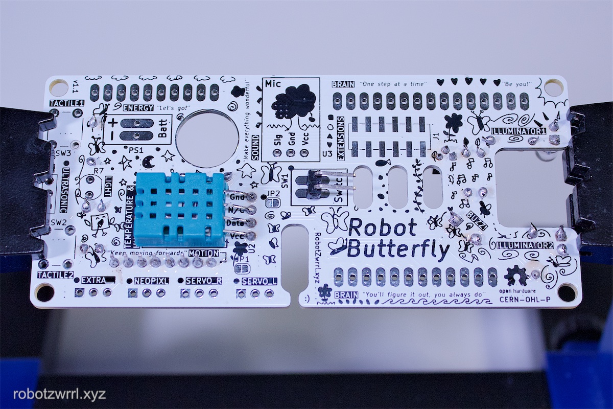
Flip the board to front side facing up.
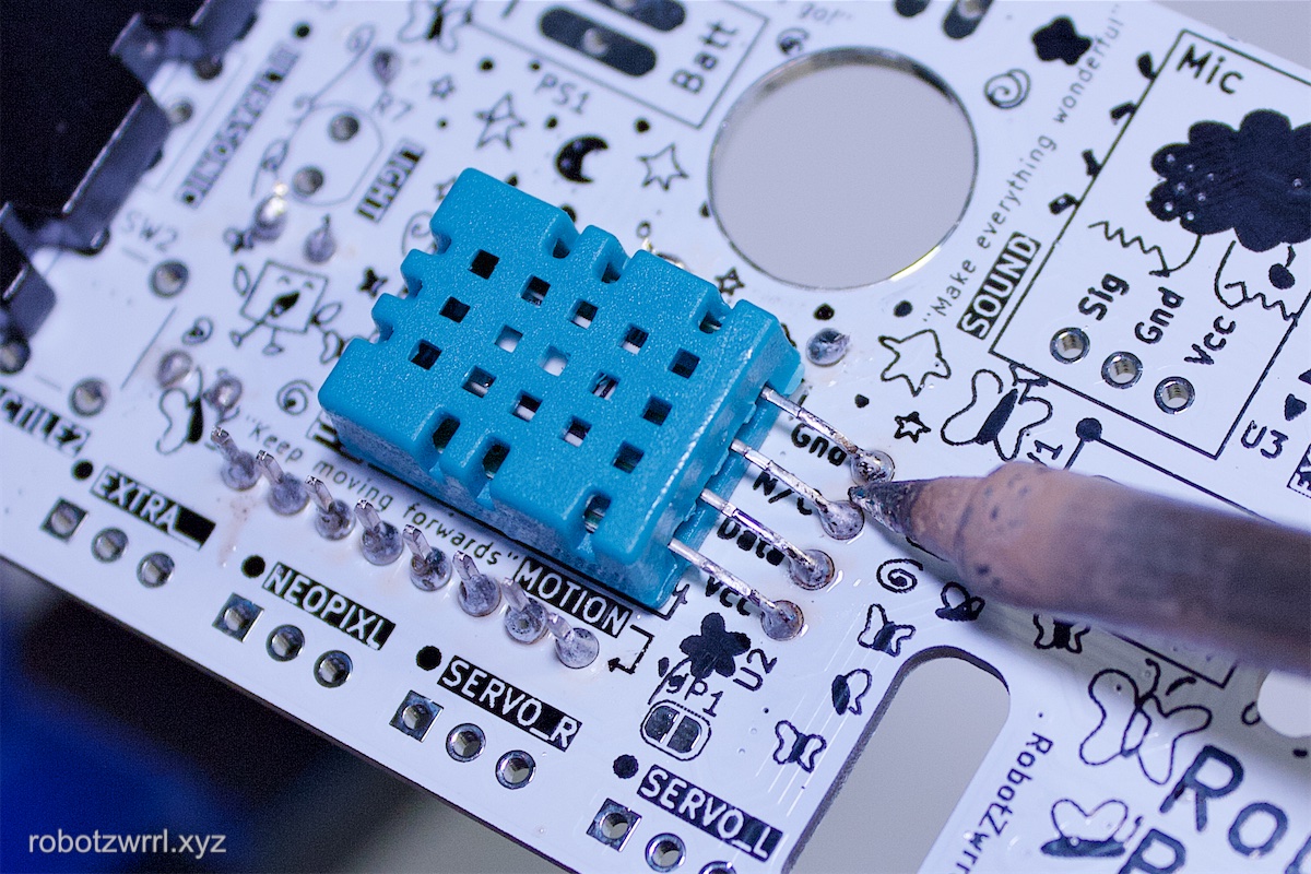
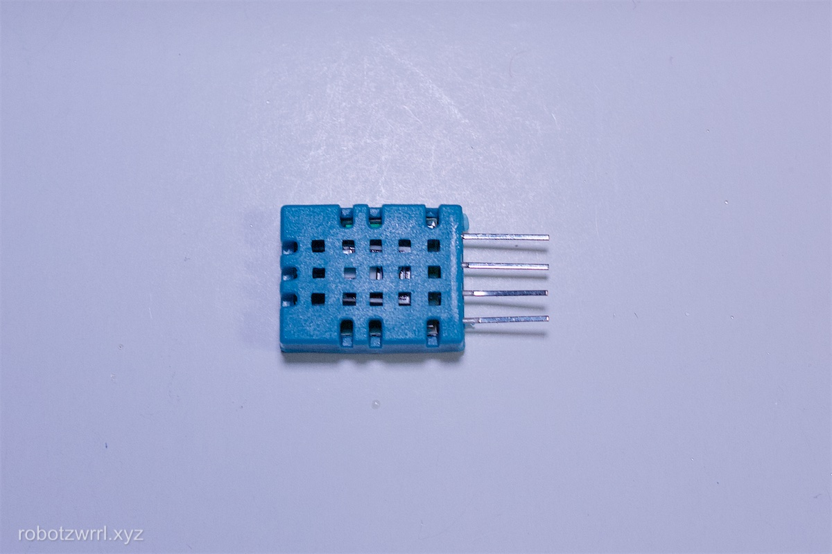
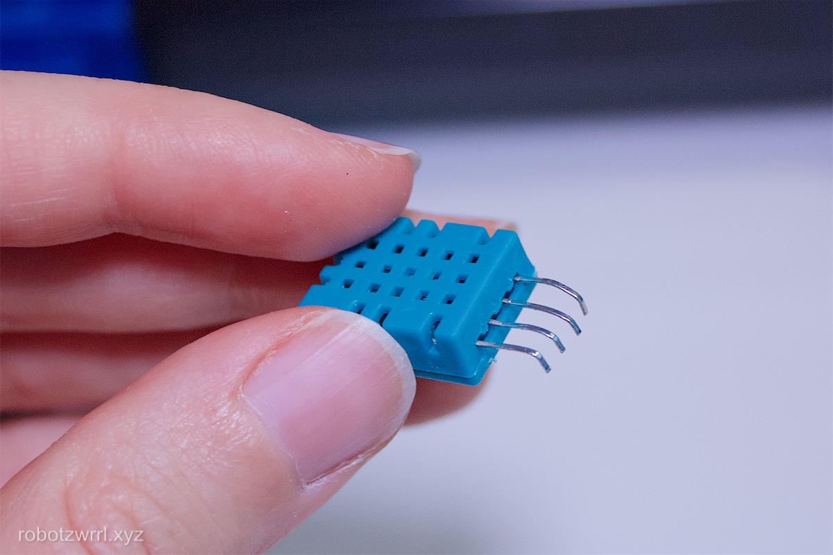
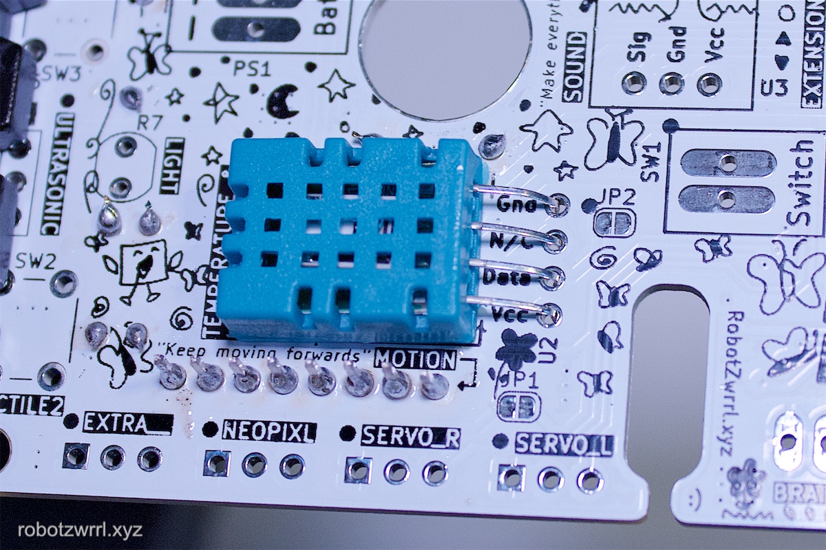
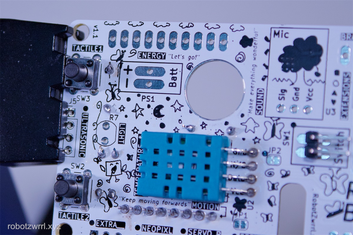
Solder the temperature and humidity sensor, known as the DHT11. This goes into spot U2. The blue portion should be facing up and flat on the surface. It may be helpful to use needlenose pliers to bend the ends of the legs.
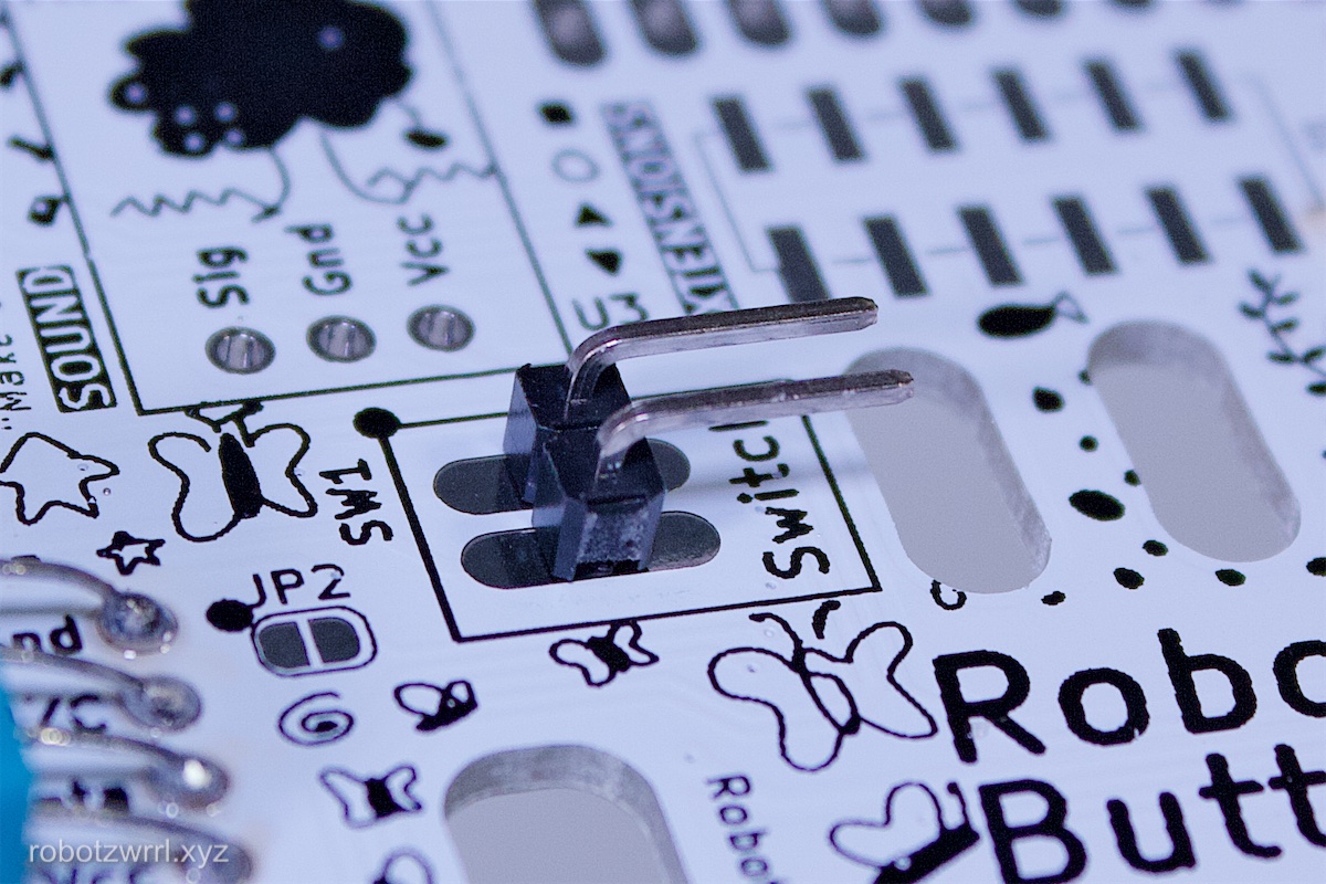
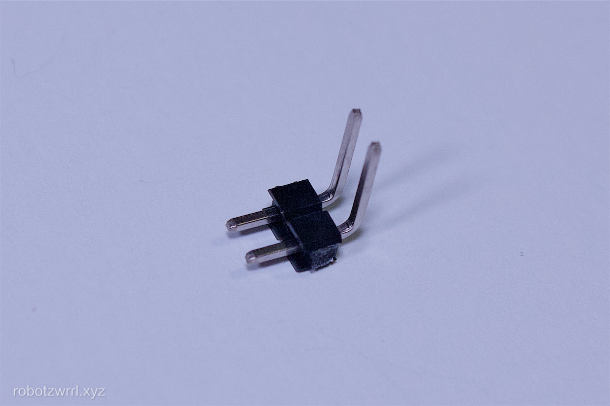
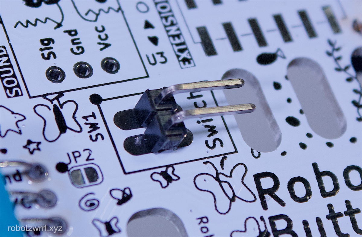
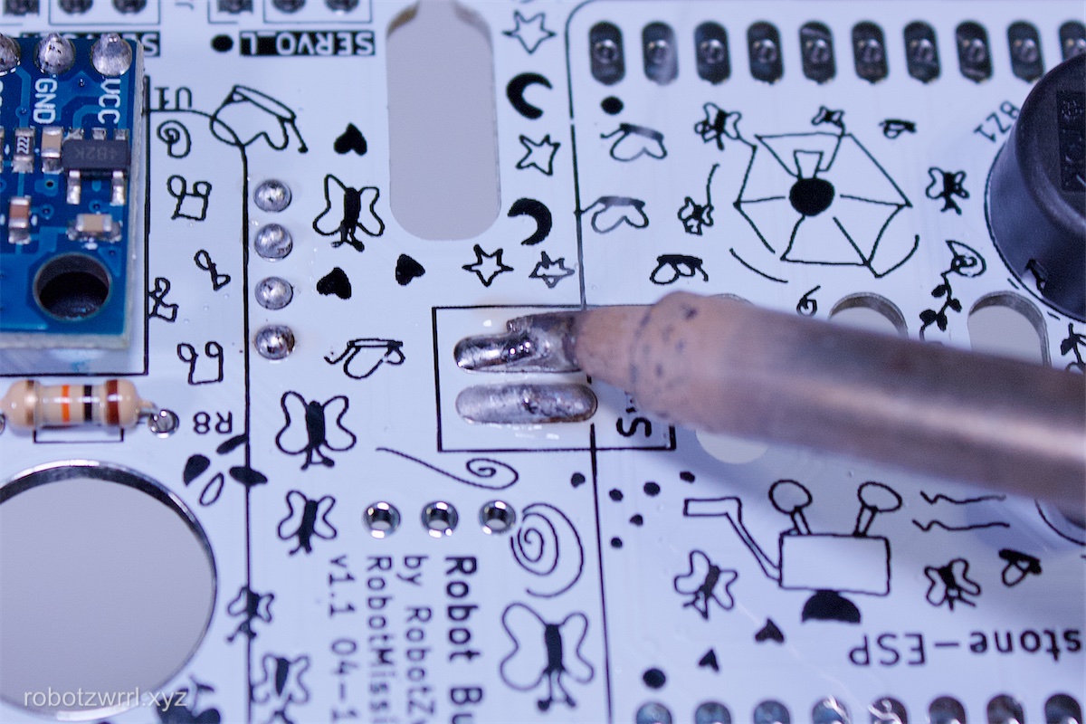
Solder the 2 pin right angle header (M): SW1. The shroud should be facing up. The leads should be pointing towards the slots. Please refer to photos for clarification.
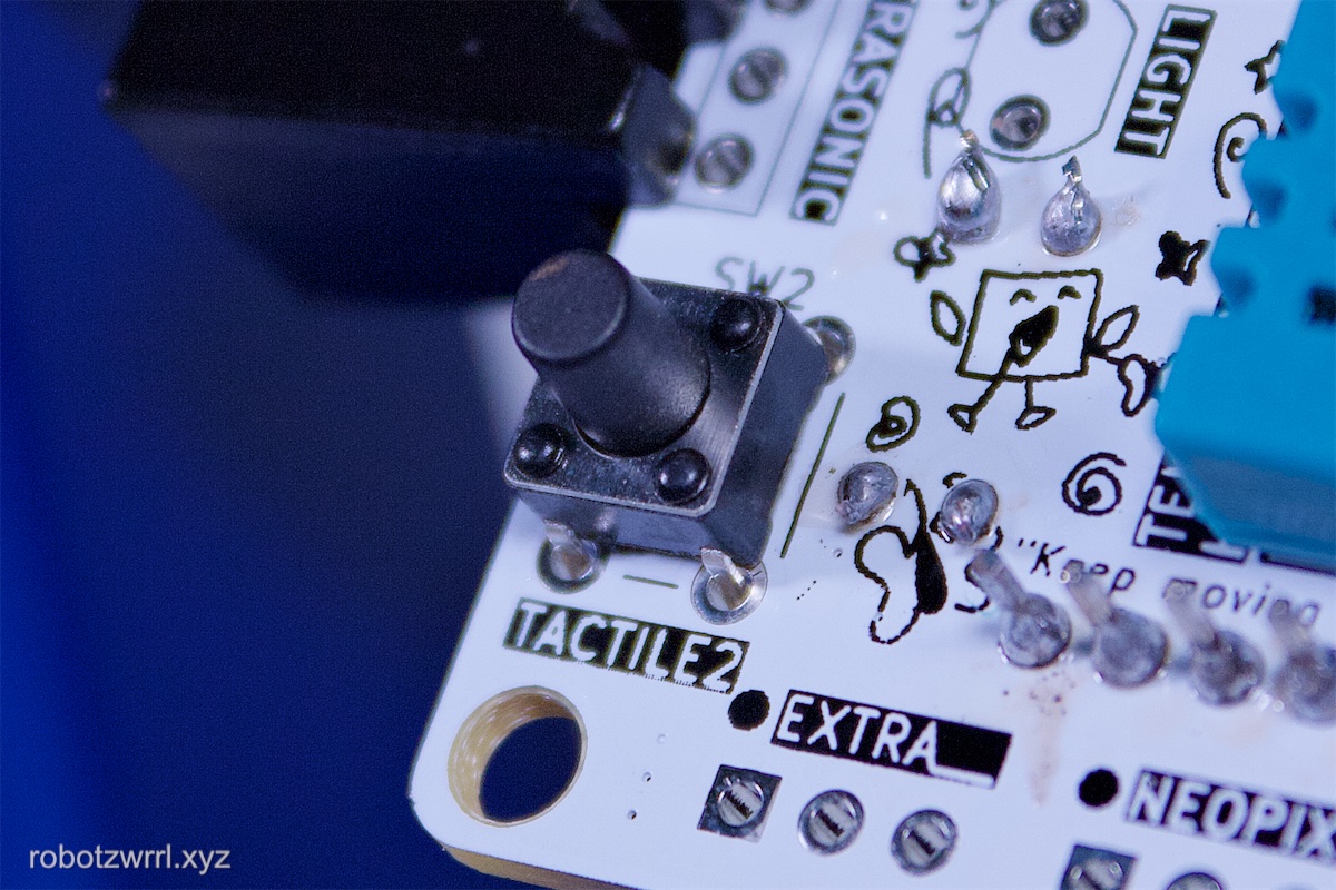
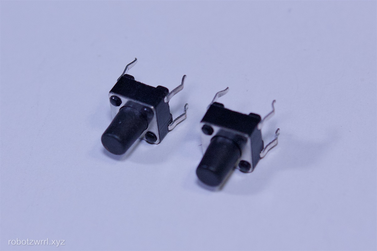
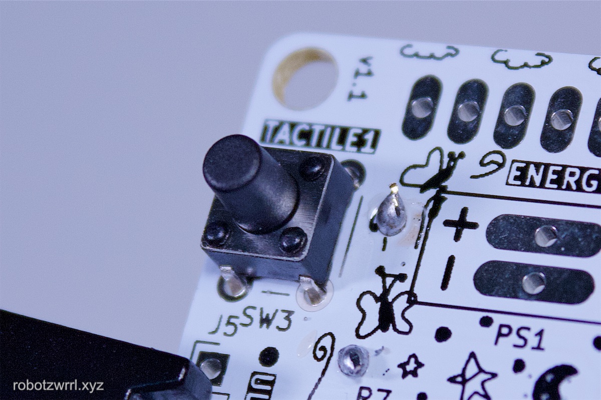
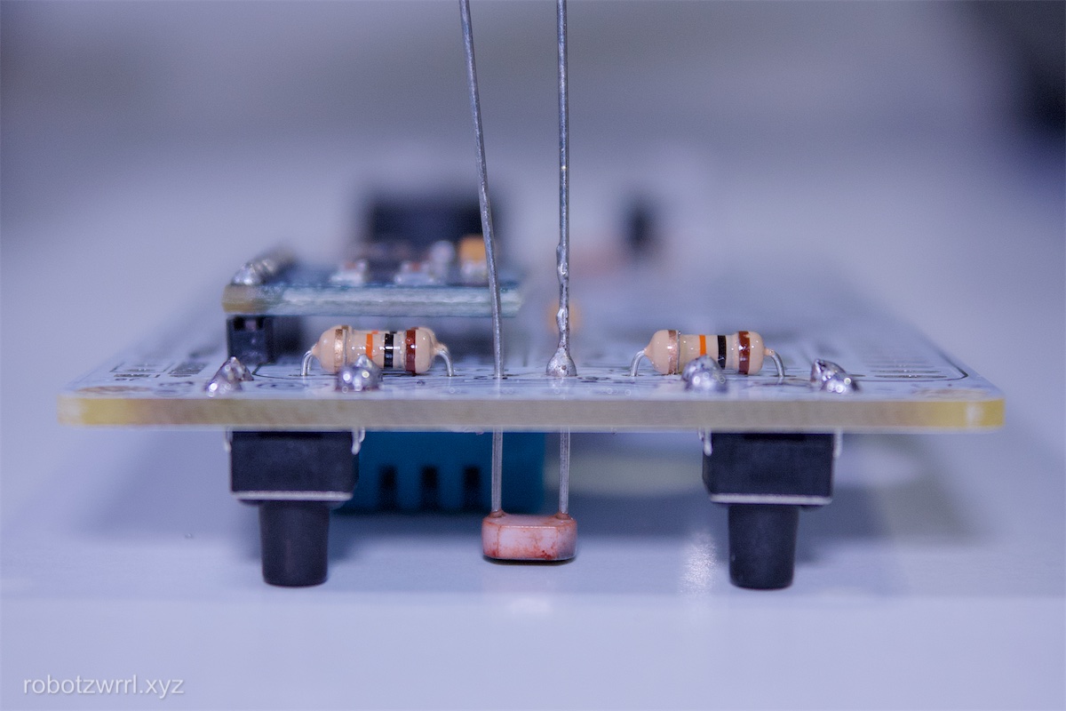
Solder the tactile buttons: SW2, SW3. The buttons should be pointing up.
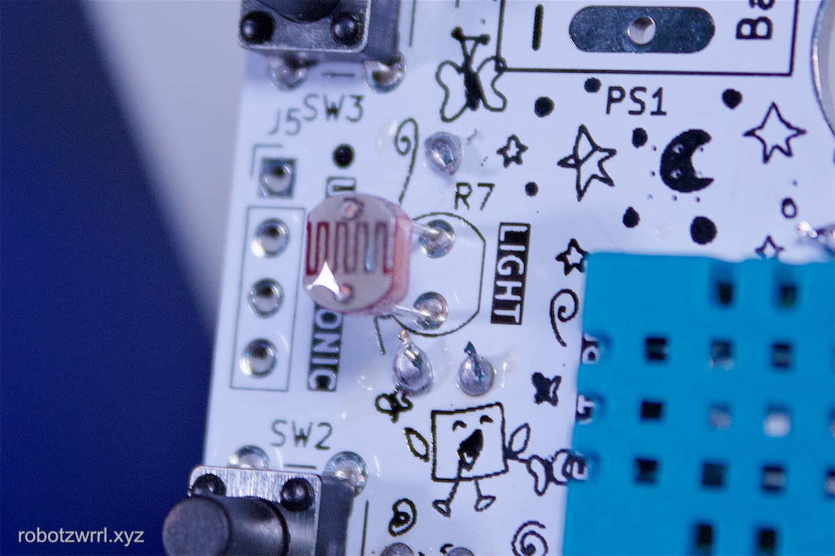
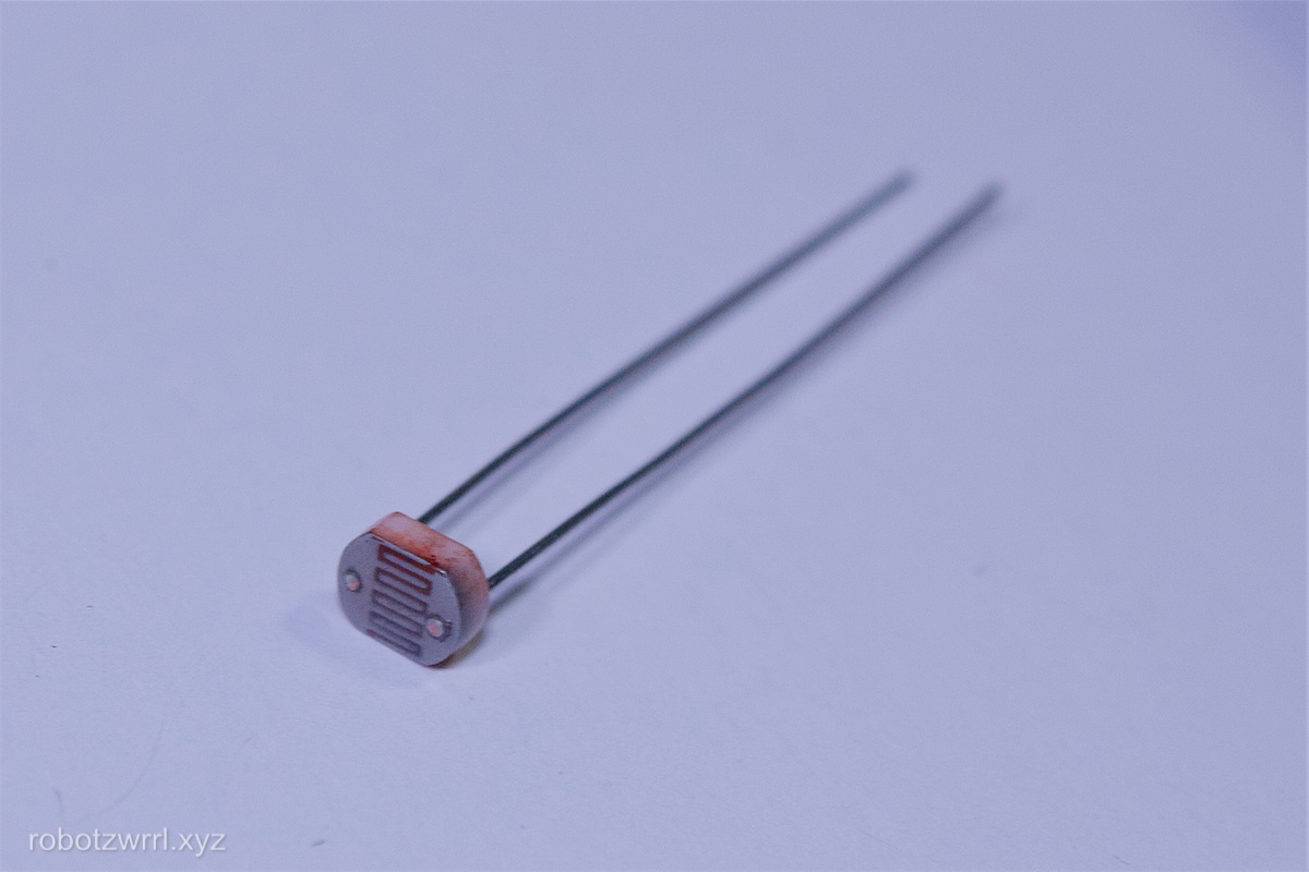
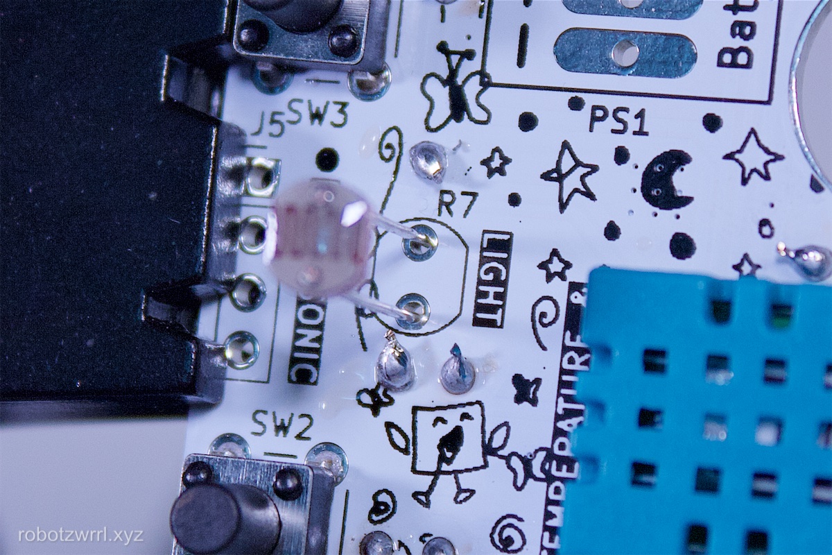
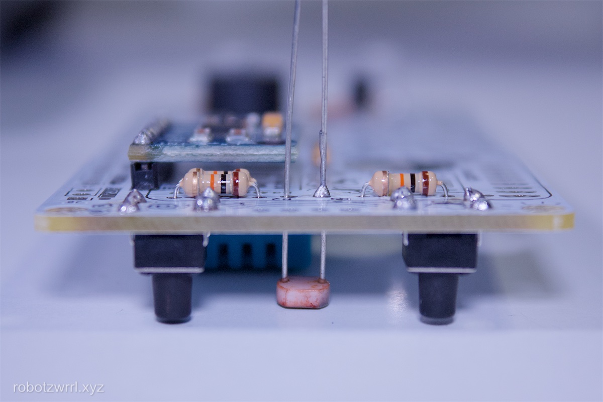
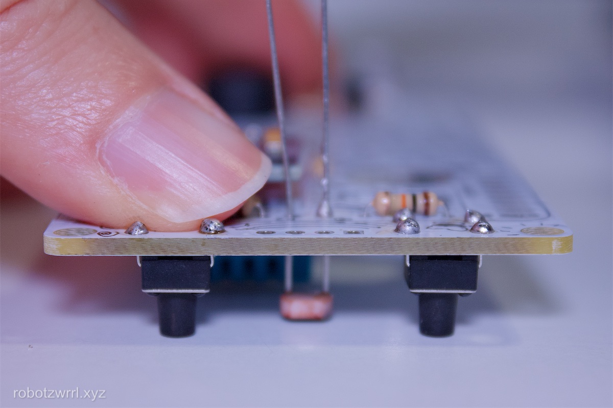
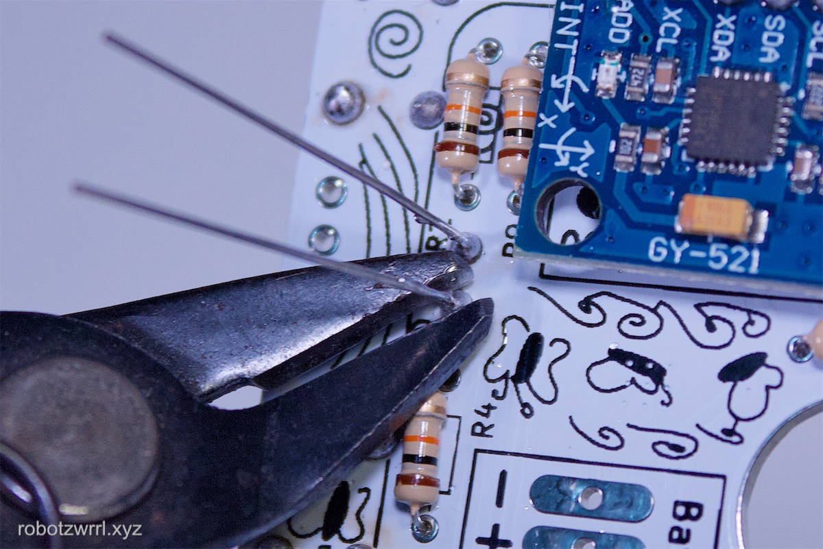
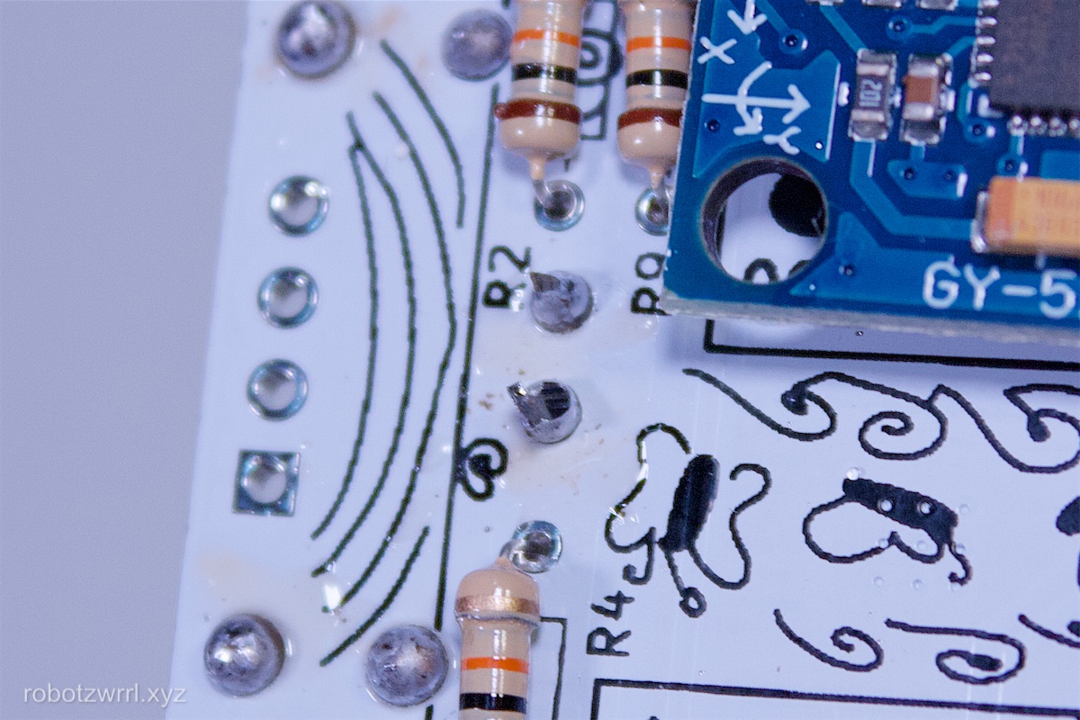
Solder the photocell: R7. The height of the sensor should be the same height as the tactile buttons. Here’s a trick on how to do it:
Insert the photocell leads through the R7 pads. Flip the board over. Balance the board such that the tactile buttons are flat on the surface. Adjust the photocell so it is flush with the surface. Solder one of the pads. Touch the pad with the soldering iron again and make any fine tuning adjustments to the height. Flip the board over and inspect. The photocell should not be taller than the tactile buttons. When correct, flip board over and solder the remaining pad. This trick will help the photocell be seated closer to the aperture pattern on the laser cut lid piece.
Page last updated: April 28 2025 11:04:08.